Loading…
Pipe Shields Inc. manufactures pre-insulated pipe supports, slides, guides and anchors and is a subsidiary of Piping Technology and Products, Inc.
Resources
Loading…
Piping Design and Analysis Influence on Pipe Support Selection and Design
Surveying a piping system? Need to change a current system?
This course is also great for…
• New Engineers, Management and Operations
• Field, Process, Maintenance and New Engineers
• Piping and Piping System Designers and/or Instructors
*This online course is approved for 8 hrs. P.E. Credits
Date: Thursday, May 3, 2018
Register for either time slot: 10:00 am OR 2:00 pm CDT
Note: Time Zone is CDT * Central Daylight Time / GMT -5h
This presentation will cover Pipe Clamps, including Hold-Down Clamps, Riser Clamps, Clevis Hangers, Yoke U-Bolt Clamps and Structural Supports. Learn how the appropriate type of pipe support is chosen based on the different design conditions. Find out how Finite Element Analysis is used in the design process and view the custom pipe supports designed for extreme applications.
After registering, you will receive a confirmation email containing information about joining the webinar.
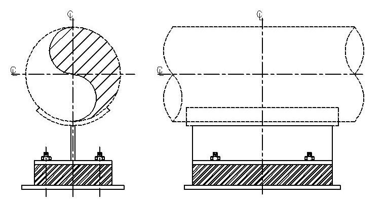
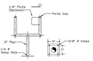
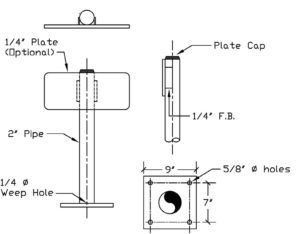
SIZE RANGE: For use with 1/2” through 72”, most designs. Insulation thicknesses of 1”, 1 1/2”, 2”, 2 1/2”, 3”, 3 1/2”, 4”, and larger sizes where specified.
HOW TO SIZE: Refer to “Insulation Chart”, on the next page for sizing the insulation material.
ORDERING: Specify figure number, pipe size, insulation thickness, and insulating material.
Example:
PTP-4700-4-3-B
• 4700 = Type of insulated shoe (cold)
• 4 = Nominal pipe size
• 3 = Insulation thickness
• B = Insulating material (micarta®)
Piping Technology & Products, Inc. is a manufacturer and fabricator of all types of pipe supports. This section is devoted to variable spring and constant supports. In addition to the many standard supports you will find described here, we will design and custom-build special supports to meet your specific needs. In fact, many of the items you will see in this catalog were developed for the specific requirements of a customer who could not use the standard designs available in our industry. If you do not find what you need, or if you need technical advice, please contact us.
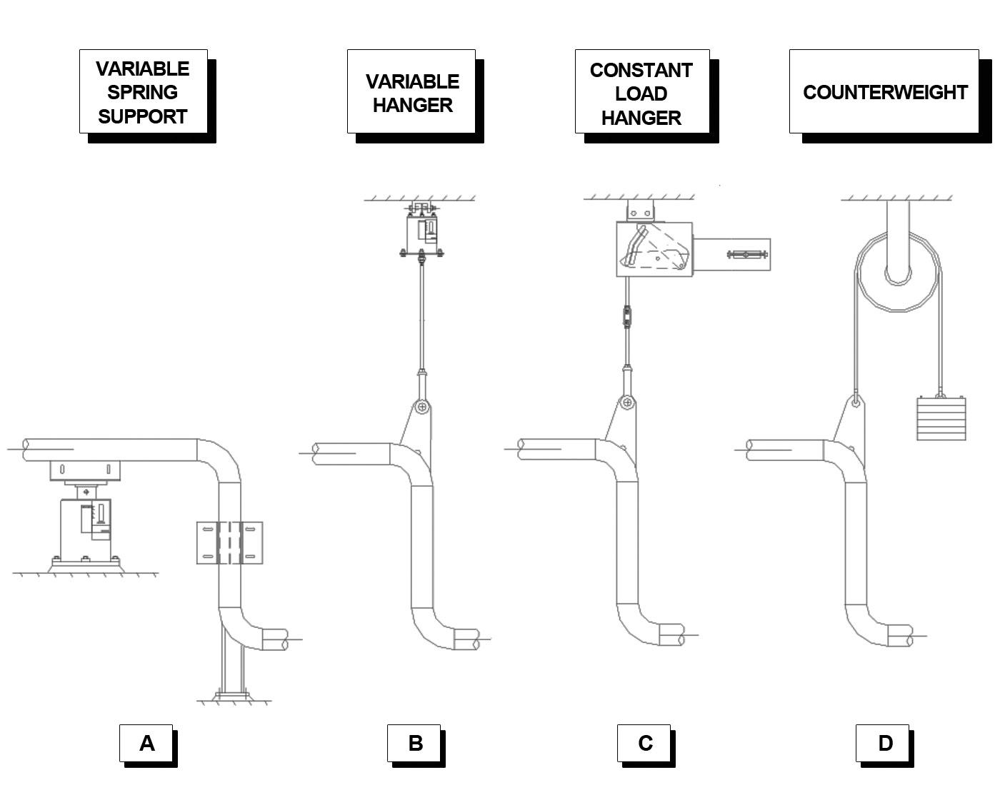
Designers of piping systems must provide for the pull of gravity and for movement due to thermal expansion. Spring supports, variables, and constants are devices which are cost-effective and structurally sound in solving certain pipe support problems. Constants are more expensive, so they are usually used in more critical applications, described in detail in the Constant Spring Hangers section.
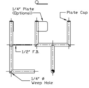
The illustration below shows three applications of spring supports and one involving a counterweight. In figure (A), a variable spring support is placed under the horizontal pipe just left of a vertical section which has a guide and rigid support. In (B) a variable hanger is suspended from above and connected to the elbow above the vertical section. In (C) the designer has chosen a constant load hanger because the vertical section is connected to a critical nozzle. A counterweight such as shown in (D) may be useful when pipe weights are unknown and must be balanced in the field. Piping Technology & Products, Inc. will calculate and custom-fabricate such counterweights for you.
Download Slide Plates General Information
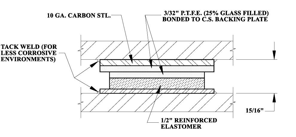
Slide bearing plates are a very cost-effective way of providing for movement of mechanical systems. Piping Technology & Products, Inc. supplies slide bearing plates for a variety of applications including support of piping, heavy equipment such as pressure vessels, and structural steel members. The plates provide a surface with a low coefficient of friction which can be attached to a supporting structure. This combination provides support while simultaneously allowing an object to move (slide) freely along the supporting surface.
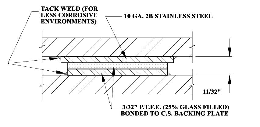
Most designers use the “sandwich” concept when applying slide plates to their systems. Diagram A (on Page 192) shows a “sandwich” composed of two identical slide plates, one on top and another on the bottom. Each slide plate is composed of two components: a metal backing plate (which is like the bun of the “sandwich”) and a low coefficient of friction material which is bonded to the metal backing plate.
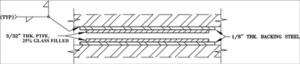 Diagram A: Sandwich Concept
In a typical application, a slide bearing plate is welded to a structural steel member which is strong enough to provide the required support, but whose coefficient of friction is too high. When the pipe supported by the member moves (due to thermal expansion, for example) it slides across the surface of the bearing plate without contacting the steel beam. To return to our “sandwich” metaphor, the top half of the “sandwich” is bonded to the pipe, and the bottom half to the steel beam.
One combination of materials that we recommend is that of PTFE, 25% glass filled, bonded to stainless steel. Both materials resist oxidation and have long lives even in stressful environments. For large slide plates, galvanized steel can be used in place of stainless to reduce the cost.
|
Slide Plate Selection Chart
|
|||
|
Temperature
|
Max Load
|
Coefficient of Friction
|
|
| PTFE, 25% Glass Filled |
-320°F to +500°F
|
Loads up to 2,000 PSI
|
.01 to .2 |
| Bronzphite® |
up to 1,100°F
|
Loads up to 5,000 PSI
|
.15
|
| Graphite |
+1,000°F Air & +3,000°F Inert
|
Loads up to 2,000 PSI
|
.15
|
| Stainless Steel |
up to 1500°F
|
Loads up to 5,000 PSI
|
0.08 @ Min. Pressure
0.06 @ Max. Pressure
(polished) |
| Marinite |
+400°F to +800°F
|
100 PSI to 2,500 PSI
|
0.08 @ Min. Pressure
0.06 @ Max. Pressure
|
Assembly Basics
Slide plates are usually arranged in what is known as a ‘sandwich’ formation, which consists of an upper slide plate component and a lower slide plate component.
The lower slide plate may also be welded to a stationary support (i.e. structural steel member), which grounds the plate, while the other plate is attached to the moving component directly. As the system moves, friction is transferred at the intersection of the two plates.
When ordering, always specify the dimensions of the upper and lower slide plate. As a rule, the upper slide plate should be large enough to completely cover the lower plate at all times.
Recommended Applications / Temperature Limits
-320F to +500F with low PSI
Different plates are suited for different temperature limits. While all plates have been rigorously tested for suitability within industrial settings, understanding the particular variables of that setting is vital to purchasing the appropriate plate for each application.
TEMPERATURE CONSIDERATIONS
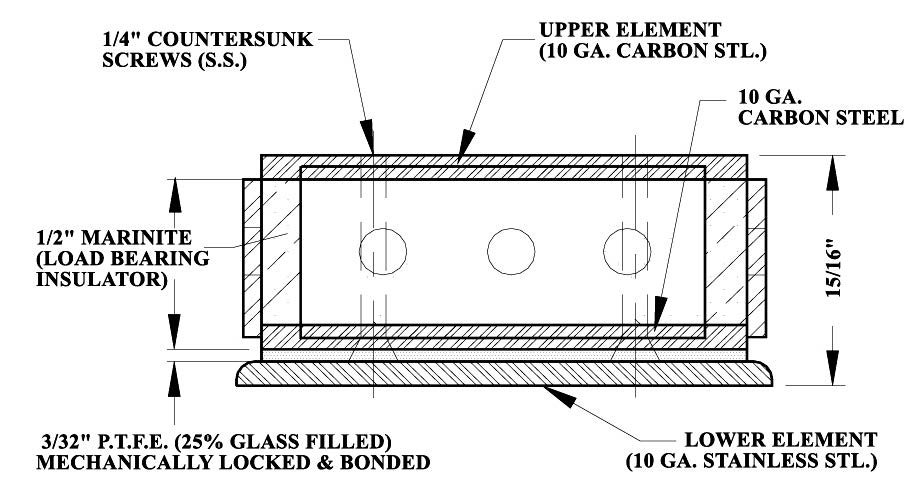
PTFE, 25% glass filled, provides a low coefficient of friction for most combinations of temperature and load. Diagram B, on Page 193, shows the recommended conditions for 3/32” PTFE, 25% glass filled. For most applications, PTFE, 25% glass filled, is adequate when the temperature is less than 400 °F. When the slide bearing plate must function at higher temperatures, graphite can be used instead of PTFE, 25% glass filled. The load-bearing capacity of graphite is not sensitive to increases in temperature, but the adhesive used to bond the graphite to its metal backing is. It is good practice to use additional mechanical fasteners such as counter-sunk screws to help hold the graphite in place when the temperatures are above 500 °F. For combinations of temperature and load beyond the capabilities of graphite, special designs must be considered.
ATTACHMENT CONSIDERATIONS
Welding is the most common method of attaching the slide bearing plate to supporting metal structures. When this approach is used a slide plate must be designed with a “lip” since the welding’s extreme temperature may break the bond between the low-friction material and the metal plate. A 1/4” “lip” is adequate for most welded installations. When welding cannot be used (for safety or other reasons) to attach the slide plates, bolting is the most common substitute.
Before we begin constructing your slide bearing plates, we need to know the following:
• The material you desire for the low-friction surface, based on the highest combinations of temperature and load the component will experience.
• The desired size and shape for the low-friction surface.
• The type of metal, size, and shape you desire for the backing steel. Most designers choose galvanized or stainless steel.
Slide bearing plates are components of many products Piping Technology & Products, Inc. supplies such as guided pipe shoes and upthrust constants. As a result, we have extensive experience in bonding PTFE, 25% glass filled, and graphite to metal plates. Modern adhesives are adequate for most applications. However, mechanical fasteners such as countersunk screws can be added when needed. If you have unique applications, we will be happy to custom design a practical solution for your application.
Slide Plates for Higher Load Capacities
Notes:
1. Pressure range: 75 PSI to 2,200 PSI
2. Temperature range: -320 °F to 400 °F
3. Alternate backing materials are available.
Slide Plates for Deflection & Expansion at Higher Loads
Notes:
1. Pressure range: 75 PSI to 1,500 PSI
2. Temperature range: -50 °F to 200 °F
3. Alternate thicknesses of reinforced elastomer available.
Slide Plates For Welding To Mating Surfaces

Notes:
1. Pressure range: 75 PSI to 2,000 PSI
2. Temperature range: -320 °F to 400 °F
3. Alternate backing materials are available.
Slide Plates For High Temperature & High Load Bearing
Notes:
1. Pressure range: 100 PSI to 2,500 PSI
2. Temperature range 1/2” insulator: 400 °F to 800 °F
3. Coefficient of friction:
0.08 @ min. pressure
0.06 @ max. pressure
Piping Technology & Products, Inc. maintains an extensive inventory of components required for pipe hanger and
support assemblies. Most of these are industry standards that have been used by piping designers for many
years. One of the value-added services we provide is assembly and tagging of units before shipping so field crews
can install them with minimal effort. Since we work with these materials daily, it is easier for us to do assemblies and
verify components and dimensions than it is for a field crew, for whom installing pipe supports is only one of many
tasks to be performed on a given workday.
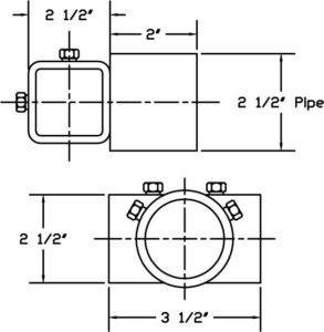
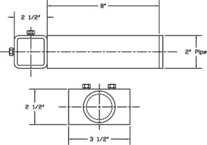
Many assemblies are attached to the pipe with clamps. Our inventories include all types of clamps made from
carbon steel with galvanized and black finishes. We can fabricate clamps from alloy steels for high-temperature
applications in which standard clamps are not adequate. When ordering clamps, please add an “A” to the figure
number of any items to be fabricated from alloy material. We have included a chart to help with the specification of
special clamps for high-temperatures and heavy loads.
To compensate for pipe movement, a designer may choose from a variety of clevis hangers, roller hangers, and
adjustable bands to support the pipe. These are linked to the supporting structure with rods and other hardware
components. Beam attachments and other accessories are attached to the supporting structure to complete the
assembly. All of these components must be strong enough to support the loads in the environment where they are
installed. Galvanized components are often used to resist corrosion.
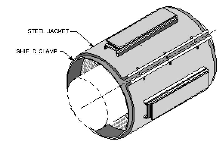
Saddle coverings are used with insulated pipes in order to provide protection to the insulation at points of support.
Roller stands, elbow supports, and other items can be supplied in adjustable models which allow field crews to make
easy installations.
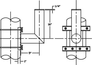
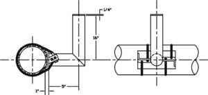
Hold-downs are special clamping supports used on pipes that are subject to vibrations and stresses, such as those
near compressors. The hold-downs dampen these forces by transferring them to the supporting structure and thus
protect the piping system.
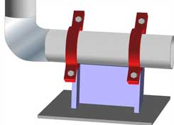
Pipe Saddles & 30″ Galvanized Riser Clamp
| NOMINAL INSULATION THICKNESS (in.) | INSULATION O.D. (in.) | APPROX. INSULATION THICKNESS (in.) |
Pipe size: 1/2" (O.840 O.D.) |
||
| 1 | 2 7/8 | 1 |
| 1 1/2 | 4 | 1 9/16 |
| 2 | 5 | 2 1/16 |
| 2 1/2 | 6 5/8 | 2 7/8 |
| 3 | 7 5/8 | 3 3/8 |
| 3 1/2 | 8 5/8 | 3 7/8 |
| 4 | 9 5/8 | 4 3/8 |
Pipe size: 3/4" (1.050 O.D.) |
||
| 1 | 2 7/8 | 7/8 |
| 1 1/2 | 4 | 1 7/16 |
| 2 | 5 | 1 15/16 |
| 2 1/2 | 6 5/8 | 2 3/4 |
| 3 | 7 5/8 | 3 1/4 |
| 3 1/2 | 8 5/8 | 3 3/4 |
| 4 | 9 5/8 | 4 1/4 |
Pipe size: 1" (1.315 O.D.) |
||
| 1 | 3 1/2 | 1 1/16 |
| 1 1/2 | 4 1/2 | 1 9/16 |
| 2 | 5 9/16 | 2 1/8 |
| 2 1/2 | 6 5/8 | 2 5/8 |
| 3 | 7 5/8 | 3 1/8 |
| 3 1/2 | 8 5/8 | 3 5/8 |
| 4 | 9 5/8 | 4 1/8 |
Pipe size: 1 1/4" (1.66 O.D.) |
||
| 1 | 3 1/2 | 15/16 |
| 1 1/2 | 5 | 1 11/16 |
| 2 | 5 9/16 | 1 15/16 |
| 2 1/2 | 6 5/8 | 2 1/2 |
| 3 | 7 5/8 | 3 |
| 3 1/2 | 8 5/8 | 3 1/2 |
| 4 | 9 5/8 | 4 |
Pipe size: 1 1/2" (1.90 O.D.) |
||
| 1 | 4 | 1 1/16 |
| 1 1/2 | 5 | 1 9/16 |
| 2 | 6 5/8 | 2 3/8 |
| 2 1/2 | 7 5/8 | 2 7/8 |
| 3 | 8 5/8 | 3 3/8 |
| 3 1/2 | 9 5/8 | 3 7/8 |
| 4 | 10 3/4 | 4 7/16 |
Pipe size: 2" (2 3/8" O.D.) |
||
| 1 | 4 1/2 | 1 1/16 |
| 1 1/2 | 5 9/16 | 1 9/16 |
| 2 | 6 5/8 | 2 1/8 |
| 2 1/2 | 7 5/8 | 2 5/8 |
| 3 | 8 5/8 | 3 1/8 |
| 3 1/2 | 9 5/8 | 3 5/8 |
| 4 | 10 3/4 | 4 3/16 |
Pipe size: 2 1/2" (2 7/8" O.D.) |
||
| 1 | 5 | 1 1/16 |
| 1 1/2 | 6 5/8 | 1 7/8 |
| 2 | 7 5/8 | 2 3/8 |
| 2 1/2 | 8 5/8 | 2 7/8 |
| 3 | 9 5/8 | 3 3/8 |
| 3 1/2 | 10 3/4 | 3 15/16 |
| 4 | 11 3/4 | 4 7/16 |
Pipe size: 3" (3 1/2" O.D.) |
||
| 1 | 5 9/16 | 1 |
| 1 1/2 | 6 5/8 | 1 9/16 |
| 2 | 7 5/8 | 2 1/16 |
| 2 1/2 | 8 5/8 | 2 9/16 |
| 3 | 9 5/8 | 3 1/16 |
| 3 1/2 | 10 3/4 | 3 5/8 |
| 4 | 11 3/4 | 4 1/8 |
Pipe size: 3 1/2" (4" O.D.) |
||
| 1 | 6 5/8 | 1 5/16 |
| 1 1/2 | 7 5/8 | 1 13/16 |
| 2 | 8 5/8 | 2 5/16 |
| 2 1/2 | 9 5/8 | 2 13/16 |
| 3 | 10 3/4 | 3 3/8 |
| 3 1/2 | 11 3/4 | 3 7/8 |
| 4 | 12 3/4 | 4 3/8 |
Pipe size: 4" (4 1/2" O.D.) |
||
| 1 | 6 5/8 | 1 1/16 |
| 1 1/2 | 7 5/8 | 1 9/16 |
| 2 | 8 5/8 | 2 1/16 |
| 2 1/2 | 9 5/8 | 2 9/16 |
| 3 | 10 3/4 | 3 1/8 |
| 3 1/2 | 11 3/4 | 3 5/8 |
| 4 | 12 3/4 | 4 1/8 |
Pipe size: 4 1/2" (5" O.D.) |
||
| 1 | 7 5/8 | 1 5/16 |
| 1 1/2 | 8 5/8 | 1 13/16 |
| 2 | 9 5/8 | 2 5/16 |
| 2 1/2 | 10 3/4 | 2 7/8 |
| 3 | 11 3/4 | 3 3/8 |
| 3 1/2 | 12 3/4 | 3 7/8 |
| 4 | 14 | 4 1/2 |
Pipe size: 5" (5 9/16" O.D.) |
||
| 1 | 7 5/8 | 1 |
| 1 1/2 | 8 5/8 | 1 1/2 |
| 2 | 9 5/8 | 2 |
| 2 1/2 | 10 3/4 | 2 9/16 |
| 3 | 11 3/4 | 3 1/16 |
| 3 1/2 | 12 3/4 | 3 9/16 |
| 4 | 14 | 4 3/16 |
Pipe size: 6" (6 5/8" O.D.) |
||
| 1 | 8 5/8 | 15/16 |
| 1 1/2 | 9 5/8 | 1 7/16 |
| 2 | 10 3/4 | 2 |
| 2 1/2 | 11 3/4 | 2 1/2 |
| 3 | 12 3/4 | 3 |
| 3 1/2 | 14 | 3 5/8 |
| 4 | 15 | 4 1/8 |
Pipe size: 7" (7 5/8" O.D.) |
||
| 1 | 9 5/8 | 1 |
| 1 1/2 | 10 3/4 | 1 1/2 |
| 2 | 11 3/4 | 2 |
| 2 1/2 | 12 3/4 | 2 1/2 |
| 3 | 14 | 3 1/8 |
| 3 1/2 | 15 | 3 5/8 |
| 4 | 16 | 4 1/8 |
Pipe size: 8" (8 5/8" O.D.) |
||
| 1 | 10 3/4 | 1 1/16 |
| 1 1/2 | 11 3/4 | 1 1/2 |
| 2 | 12 3/4 | 2 |
| 2 1/2 | 14 | 2 5/8 |
| 3 | 15 | 3 1/8 |
| 3 1/2 | 16 | 3 5/8 |
| 4 | 17 | 4 1/8 |
Pipe size: 9" (9 5/8" O.D.) |
||
| 1 | 11 3/4 | 1 1/16 |
| 1 1/2 | 12 3/4 | 1 1/2 |
| 2 | 14 | 2 |
| 2 1/2 | 15 | 2 5/8 |
| 3 | 16 | 3 1/8 |
| 3 1/2 | 17 | 3 5/8 |
| 4 | 18 | 4 1/8 |
Pipe size: 10" (10 3/4" O.D.) |
||
| 1 | 12 3/4 | 1 |
| 1 1/2 | 14 | 1 9/16 |
| 2 | 15 | 2 1/16 |
| 2 1/2 | 16 | 2 9/16 |
| 3 | 17 | 3 1/16 |
| 3 1/2 | 18 | 3 9/16 |
| 4 | 19 | 4 1/16 |
Pipe size: 11" (11 3/4" O.D.) |
||
| 1 | 14 | 1 1/8 |
| 1 1/2 | 15 | 1 9/16 |
| 2 | 16 | 2 1/16 |
| 2 1/2 | 17 | 2 9/16 |
| 3 | 18 | 3 1/16 |
| 3 1/2 | 19 | 3 9/16 |
| 4 | 20 | 4 1/16 |
Pipe size: 12" (12 3/4" O.D.) |
||
| 1 | 15 | 1 1/8 |
| 1 1/2 | 16 | 1 9/16 |
| 2 | 17 | 2 1/16 |
| 2 1/2 | 18 | 2 9/16 |
| 3 | 19 | 3 1/16 |
| 3 1/2 | 20 | 3 9/16 |
| 4 | 21 | 4 1/16 |
Pipe size: 14" (14" O.D.) |
||
| 1 | 16 | 2 |
| 1 1/2 | 17 | 1 7/16 |
| 2 | 18 | 1 15/16 |
| 2 1/2 | 19 | 2 7/16 |
| 3 | 20 | 2 15/16 |
| 3 1/2 | 21 | 3 7/16 |
| 4 | 22 | 3 15/16 |
| Large sizes, insulation O.D. are in 1" increments. Insulation thicknesses through 36" same as nominal. All dimensions rounded to the nearest 1/16". |
||
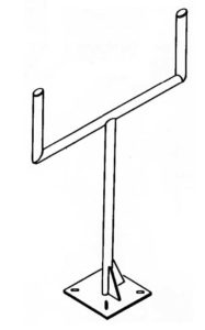
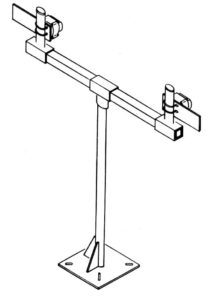
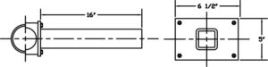
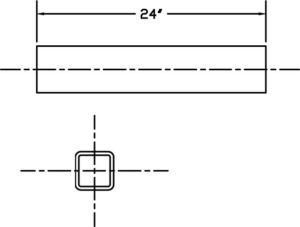
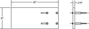
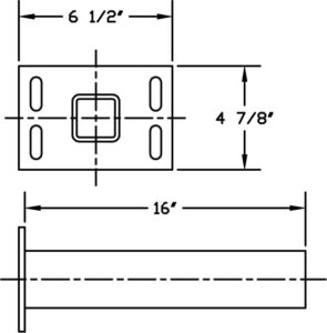
PT&P offers a complete line of adjustable instrument support components which, when combined, will create various configurations to your exact requirements or individual needs. We also provide welded instrument supports fabricated according to your specifications.
|
|
|
Primary support components are available in various mount styles, including floor mounts, wall mounts, u-bolt mounts, and cable mounts. These primary mounts can be used independently or together with secondary components to construct various packages for individual needs.
|
|
|
|
|
|
|
|
|
|
|
|
|
|
|
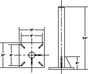
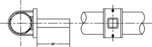
Note: The extension lengths shown on primary components are standard, other lengths can be furnished on request.
Welded instrument supports may be fabricated in any desired configuration according to the customer’s individual requirements and design specifications.
Examples of various welded instrument support configurations:
|
|
|
|
|
|
|
Cable Mounts
|
U-Bolt Mounts
|
Wall Mounts
|
Floor Mounts
|
Secondary Supports
|
|
| Attachment: |
Attached to instrument by cable.
|
Attached to piping instrumentation.
|
Welded or bolted to support.
|
Welded or bolted to support.
|
Attached to instrument; welded or clamped on stand.
|
|
Function:
|
Support and hold instrument at fixed location.
|
Hold instrument during plant operation.
|
Support instrumentation during operations.
|
Support instrumentation during operations.
|
Used in combination with primary supports to support instrumentation.
|
|
Location:
|
Where instrument is welded to structure
|
Bolted into concrete or welded to structure.
|
Bolted to walls and other vertical surfaces.
|
Bolted on the floor or in the ground.
|
Attached to primary instrument stands, usually floor or wall mounts.
|
Marinite can be used as the insulating material in hot piping supports. The most widely known grade for Marinite is grade P. Marinite-P is most often used as structural insulation because of its high dimensional stability. Marinite-P is incombustible, provides high insulation values, and high compressive strengths and is thus appropriate in high-load and high-temperature applications. The material minimizes decay, rust, and corrosion and it resists damage during installation and provides durable service. The material acts as a suitable insulator in fireproofing and heat processing equipment applications up to 1200°F (649°C).
Major Advantages:
• High Compressive Strength.
Deflects less than 1/10 in. per inch of thickness under 4000 psi
Deflects less than 3/64 in. per inch of thickness under 2000 psi
• High Tensile strength.
• High resistance to shear and traverse forces.
Major Applications:
• Hot Line Pipe Supports in Power Generation and Process Industries
• Structural Insulation in Pipe
• Supports Backup Insulation in Rotary Kilns of Lime and Cement Plants.
• Ceramics and Foundry applications.
Coefficient of Friction:
0.08 @ minimum pressure
0.06 @ maximum pressure
Firetemp®, usually known as Super Firetemp®, is widely used as insulation for hot piping supports. It is an inorganic incombustible material. Chemically, it features a xonotlite crystal structure that results in exceptional strength and extremely low water if hydration. Super Firetemp® is composed primarily of lime, silica, and reinforcing fibers. The product is white, essentially dust-free, and contains no asbestos. It is a very good material for structural insulation inserts.
Firetemp® insulation’s major advantages and applications are given below. For more detail please see the Insulation Comparison Table.
Major Advantages:
• Exceptionally High Strength
• Low Conductivity
• Easy Application
• Zero clearance to combustibles
• Temperature Range to 1800°F
• Asbestos-Free
Major Applications:
• Hot Line Pipe Supports in Power Generation and Process Industries
• Indoor and Outdoor Piping and Equipment
• Block Insulation
• Fire rated enclosures around kitchen exhaust hood
• Fireproofing structural steel
• Fire rated walls
Foamglas® insulation is a lightweight, rigid insulation composed of millions of completely sealed glass cells. Each cell serves as an insulating agent. Foamglas® is widely used in the cryogenic and hotline pipe supports and is fabricated in various ranges of shapes, thicknesses, and sizes to meet the particular requirements of an application.
One unique advantage that Foamglas® has is its very low moisture absorption. Since Foamglas® insulation is full of closed glass cells, it resists moisture in both liquid and vapor form. This guarantees the long-term performance of the insulation. Foamglas® insulation’s resistance to moisture ensures that properly installed, it retains its original thermal efficiency.
The major advantages and applications of Foamglas® insulation are listed below. For details about the physical and mechanical properties of the Foamglas® material, please refer to the table.
Major Advantages:
•Constant Insulating Efficiency
•Fire Protection
•Corrosion Resistance
•Long-Term Dimensional Stability
•Physical Strength
Major Applications:
•Cryogenic and Hot Line Pipe Supports
•Cryogenic Tanks and Vessels
•Chilled and Hot Water Service Lines
•Overfit and Revitalize the Old Insulation
•Composite Insulation Systems for Special Conditions
| Density | Foam Glass(8 pcf) |
| Compressive Strength | 400.00 |
| Flexural Strength (flat wise with grain) (psi) | 80.00 |
| Tensile Strength (with grain)(psi) | N/A |
| Modules of Elasticity (psi) | 1.3 10^6 |
| Closed Cell Content (%) | N/A |
| Temperature (F)-Continuous Operation | 500 max. |
| K-Factor | N/A |
| Thermal Conductivity (btu/hr m^2 of) | 0.7000 |
| Shear (flat wise) (1/8″ thk.) (psi) | N/A |
| Density (lb/in^3) | 0.0046 |
| Water Absorption (%) | 0.070 |
Calcium Silicate often serves as the insulation for pipe supports in high-temperature applications. Calcium Silicate is also known as Thermo-12/Blue. It is an insulating material composed of hydrous calcium silicate which, because of its lightweight, low thermal conductivity and exceptional structural strength are ideal for the insulation of high-temperature piping and equipment. Sometimes it is also used as block insulation. The pipe insulation comes in a complete selection of sizes. Block styles are available for application to various flat and curved surface areas.
Some of Calcium Silicate’s major advantages and applications are given below:
Major Advantages:
• Temperature Range to 1200°F
• Exceptional Strength
• Low Thermal Conductivity
• Easy Application: available sizes and shapes reduce the number of required joints and make Calcium Silicate easy to work with.
• Energy Savings: low thermal conductivity provides significant energy savings.
• Adaptable: Calcium Silicate can also be used on various shapes and sizes of surfaces.
• Fire Resistant.
• Low Chloride Content: low corrosivity.
• Asbestos-Free.
Major Applications:
• Hot Line Pipe Supports in Power Generation and Process Industries.
• Indoor and Outdoor Piping and Equipment.
• Block Insulation – insulation of various flat and curved surface areas.
Polyurethane foam is one of the major components of pre-insulated pipe supports manufactured at Piping Technology & Products. Polyurethane is different from most plastic materials in that it can be tailored to meet various load requirements of varying applications. Polyurethane foams are produced by reacting an equal ratio of di- or polyisocyanurates with polyols, in the presence of water, which acts as the blowing agent. Polyisocyanurates are formed when a higher ratio of di- or polyisocyanate are mixed with the polyol. All rigid foams made from polyisocyanurate systems have some form of polyurethane in them and can be called polyurethane foam. The physical properties differ very little at high densities. Polyisocyanurate foams are used in applications where dimensional stability over 200 deg F is required. However, for cryogenic applications, where your pipeline insulation is not exposed to high temperatures, PUF is an acceptable substitution.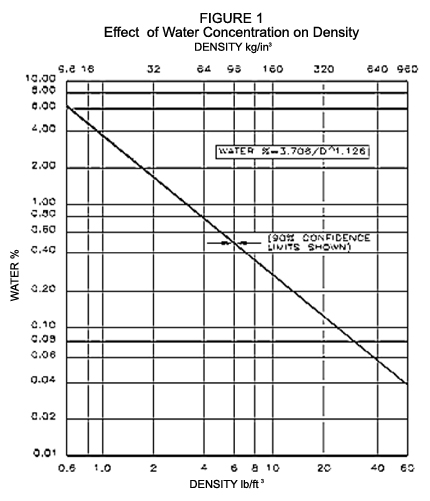
A common method used to obtain a change in load capacity is a change in density. At Piping Technology and Products, we offer 10 lbs. / ft3, 14 lbs. / ft3, and 20 lbs. / ft3 densities.
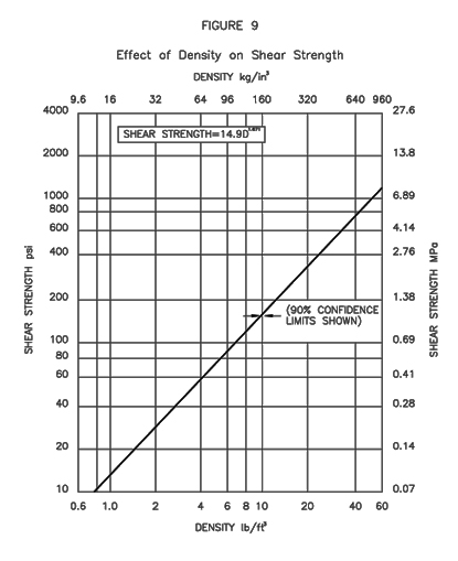
Density varies when the amount of blowing agent (water content) changes. The density of polyurethane decreases with increase in water content (See Fig. 1). This relationship can be shown as follows:
W = 3.706 / D1.126
Where: W = % of water content
D = Density of foam (lbs./ft3.)
In addition to density, the strength of a rigid urethane foam is also influenced by many factors such as catalyst, surfactant, type of mixing, the type of foaming system: base polyol and isocyanate, and the influence of each of these on the foam cell structure.
Rigid urethane foams generally have an elastic region in which stress is nearly proportional to strain. They do not exactly follow Hooke’s Law (stress is proportional to strain) because the curve is very slightly “S” shaped. Fig. 2 shows this in detail.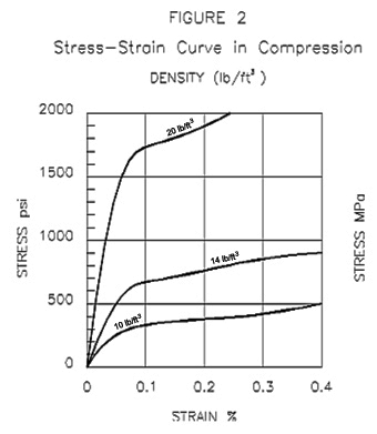
Polyurethane is anisotropic, or polyurethane is stronger in the direction of foam rise. At Piping Technology and Products, the anisotropic character or directional properties of our polyurethane is reduced by overloading the mold used to form the polyurethane. By overloading the mold, we can control the cell structure and provide uniform physical properties. A relationship between compressive strength and the density of the foam is given in Fig. 3.
Polyurethane is a thermosetting material; however, it does soften slightly with increased temperature and hardens somewhat at very low temperatures. Softening at high temperatures affects the polyurethane in two ways: (a) loss of strength properties and (b) change in foam dimensions (particularly low-density foams). Low temperatures generally have a very little effect on polyurethane properties other than to make them a little harder and more brittle. See Fig. 4 for these effects.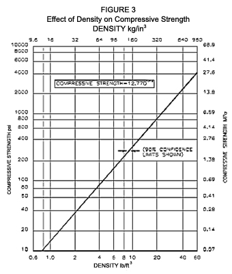
Rigid polyurethane foams have a relatively large amount of cross-linking as the foam expands. Our suppliers of the raw chemicals control the degree of cross-linking by functionality (higher functionality produces more cross-links) and molecular weight of the components in the blend. The rigid cells provide the poured foam with strength and the interior space provides low thermal conductivity. Water is used as the blowing agent for foam in this 10 to 40 lb. density range.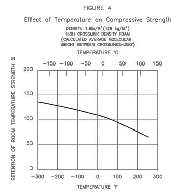
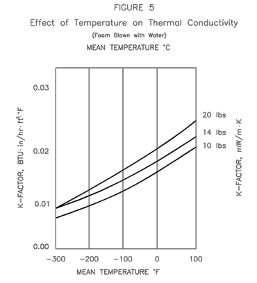
The relationship between temperature, thermal conductivity and the density of polyurethane foam is shown in Fig. 5.
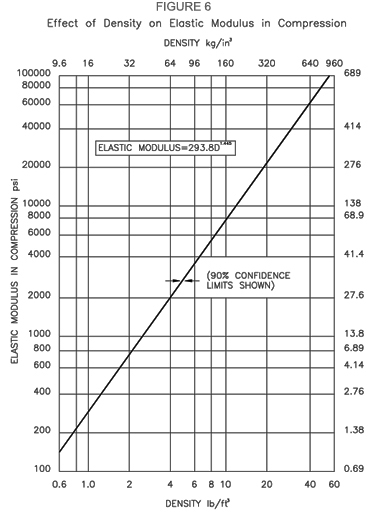
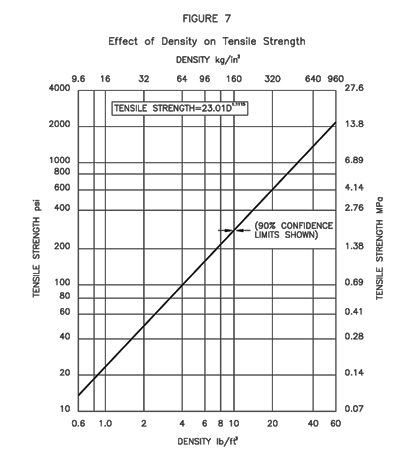
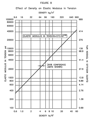
The relationships of foam’s density with its Elastic Modules in Compression, Tensile Strength, Elastic Modules in Tension, and Shear Strength are given in Figs. 6 through 9 respectively. Please see the following for the respective curves.
Piping Technology & Products has a complete manufacturing facility for production of polyurethane required for pipe supports. We invite our customers to visit our facility and observe the fabrication of insulated pipe supports of all types.
| PUF (10lb/cuft) | 200.00 | 400.00 | 300.00 | 6,000.00 | 95.00 | -300.00 | 0.08 | 0.1600 | 180.00 | 0.1157 | 0.22 |
| PUF (14lb/cuft) | 300.00 | 600.00 | 500.00 | 11,000.00 | 95.00 | -300.00 | 0.12 | 0.2000 | 200.00 | 0.1736 | 0.18 |
| PUF (20lb/cuft) | 500.00 | 1,100.00 | 600.00 | 20,000.00 | 95.00 | -300.00 | 0.14 | 0.2500 | 400.00 | 0.2893 | 0.13 |
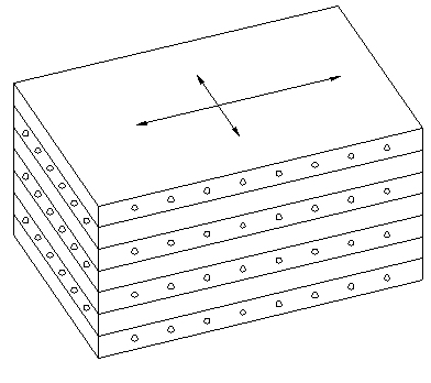
Laminated Beechwood Technical Information Permali® or Insulam® is an insulating material used in applications which require high tensile and compressive strength (see table below). In addition, due to its exceptional resistance to moisture, it serves as a suitable insulator where the support (flare lines & dummy legs) is exposed to harsh environmental elements. Permali® or Insulam® is a phenolic laminated (densified, impregnated wood) product made from carefully selected thin beechwood veneers. These wood layers are impregnated under vacuum conditions with a special synthetic resin and then densified through the application of heat and pressure. The result is a homogenous material that combines the great strength and toughness of wood fibers with the excellent stability and dielectric properties of the most advanced thermosetting. The phenolic laminated block material is furnished with cross-directional fibers as shown in Figure 10 below.
| Density | Permali |
| Compressive Strength | 30,000.00 |
| Flectual Strength (flatwise with grain) (psi) | 15,000.00 |
| Tensile Strength (with grain) (psi) | 15,000.00 |
| Modulus of Elasticity (psi) | 2.0 x 10^6 |
| Closed Cell Content (%) | N/A |
| Temperature(F)-Continuous Operation | 221.00 |
| K-Factor | N/A |
| Thermal Conductivity (btu/hr m^2 of) | 0.0018 |
| Shear (flatwise) (1/8″ thick) (psi) | 7200.00 |
| Density (lb/in^3) | 0.0469 |
| Water Absorption (%) | 0.75 |
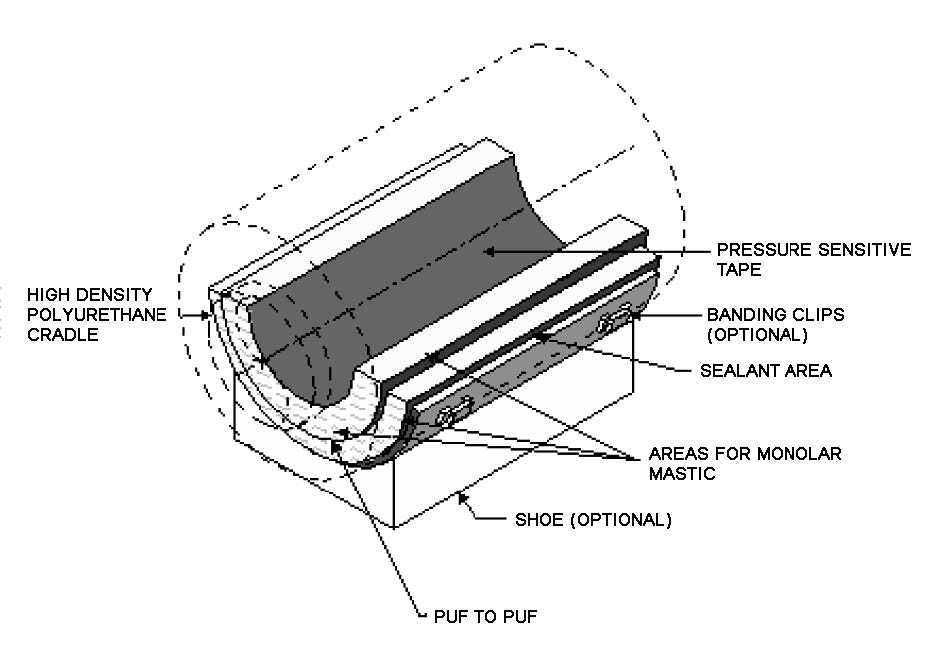
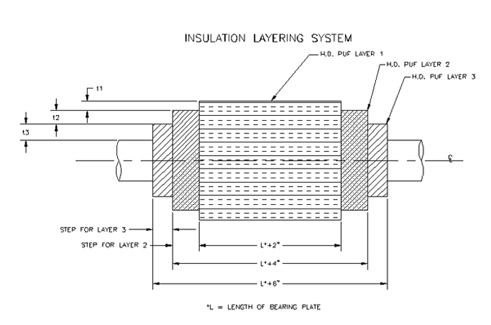
At Piping Technology and Products, we recommend multiple layers for cold shoe supports that have a total insulation thickness of four inches or greater.
In the field, cold shoes are typically mated with existing line insulation. Due to the low temperature of the pipe, moisture from the ambient air can be drawn to the pipe through gaps that may exist between the cold shoe and the line insulation. At lower temperatures, where thicker insulation is required, there is greater opportunity for moisture to be drawn to the pipe. This is because of the increased single mating surface area between the line insulation and the cold shoe.
A solution that eliminates this potential problem is providing multiple mating surfaces between the line insulation and the pipe support. Hence: When insulation thickness is four inches and greater, multiple layers provide an improved moisture seal due to steps between the different layers.
To determine the thickness of each layer, refer to our suggested layering chart on the following page. To use this table, reference the total insulation thickness to determine how many layers are suggested and how thick each layer should be.
Example: A four inch (4″) pipe that requires five inches of insulation: Referring to PT&P’s suggested layering chart, two layers are required. The first layer (inner layer) thickness is suggested to be 2″ and the second layer (the outer layer) is suggested to be 2″ thick.
Piping Technology and Products can tailor a layering system to meet the customer’s requirements. The included layering chart is only a guideline.
“Piping Technology worked countless hours of overtime, weekends, etc. to support the piping reinforcement exercise and delivered the overwhelming majority of those items on or before the required dates. In addition, Piping Technology was instrumental in designing and fabricating the hinge system used to access vessels which created a safer environment in the field.”
–Procurement Manager (LNG Project)
“I would like to express my personal appreciation for the extraordinary efforts put forth by the individuals at U.S. Bellows. When our G417 Pump piping failed suddenly during the plant startup, everything went from a normal startup to emergency status, the response by the people at your facility was immediate and highly effective. With one of our major process plants shutdown and waiting on this bellows for startup, the need and pressure to expedite the completion of this bellows was immense. The individuals at U.S. Bellows demonstrated the willingness to go the extra mile and complete the construction ahead of the original projected timeline. These actions were instrumental in helping to solve the many logistical and technical problems associated with the cleanup and startup in a timely manner.”
–Buyer (Large Refinery Project)
“Each and every support was fabricated well ahead of schedule and arrived at site before the pipe did. This eliminated the need for using temporary supports. All supports reached site with out any missing parts as all supports were pre-assembled and pre inspected by our joint inspection team and PTP QC department. PT&P was pro-active in supporting the site engineers in terms of modification of supports and replacing springs that were required due to field re-routes and changes. Our construction partner and we are equally satisfied with PT&P pipe supports and concluded that these two projects were one of the best projects they have built in the recent years.
–Pipe Stress Analysis (Combined Cycle Plant Project)
“Thank you very much for the excellent work you and your associates at PTP/USB provided on my bellows order. Although we agreed to a 10-day rush delivery, your shop responded to my project schedule and delivered 14 bellows assemblies in only 7 days from my order. This quick delivery helped us avert a scheduling conflict on a very critical project. I would be glad to recommend U.S. Bellows to anyone in need of a quality product with on-time or better delivery.”
—