Installation Steps

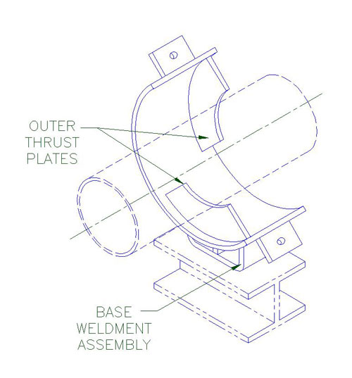
1. A) Center the base weldment assembly (bottom strap with shop welded outer thrust plates) under the applicable support location on the pipe section as shown.
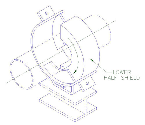
2. A) Insert the lower half shield (structural insulation material and sheet metal jacket) between the outer thrust plates and under the pipe as shown.
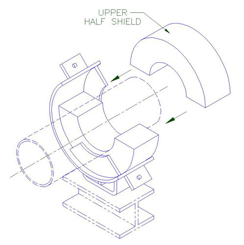
3. A) Place the upper half shield (structural insulation material and sheet metal jacket) over the pipe and lower half shield installed in Step 2 as shown.
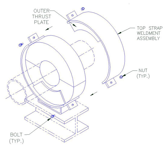
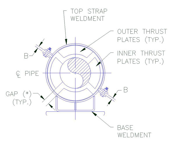
4. A) Assemble top strap weldment assembly. Top strap with shop welded outer thrust plates over the upper half shield and install the bolts through the clamp ears with nuts on top.
B) Apply the torque on the bolts, select torque value that correspond with the pipe size and model designation of the unit shown on Table 1 below. During tightening, it is recommended that the nut is turned rather than the bolt head and that the bolts be cross-torqued until the required torque has been achieved to obtain an even pressure on the structural insulation.
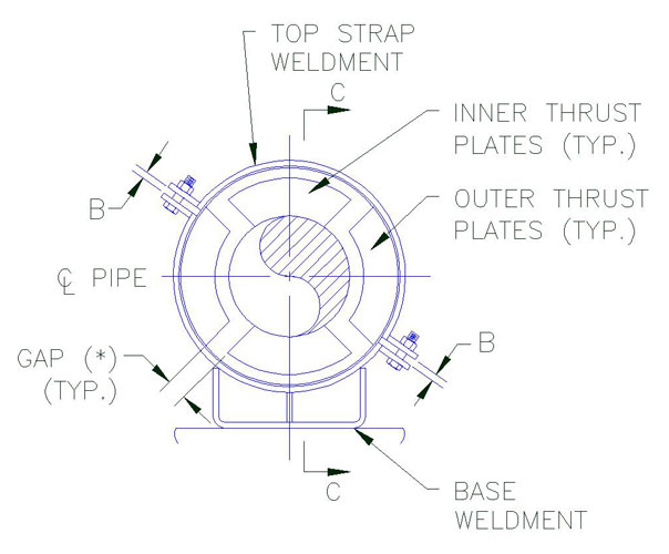
C) Ensure that the bolts are properly cross-torqued. by checking the spacing “B” between the ears to be approximately the same.
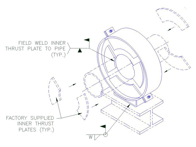
5. A) Locate and position factory supplied inner thrust plates (two on each side of the assembly) on the pipe. Locate and position the inner thrust plates on the pipe. When properly positioned weld them to the pipe shown (see Table 1 for the weld size.)
6. A) Weld base of anchor assembly to support member as shown. Select “W” (Weld Size) that correspond with the pipe size and model designation of the unit. Shown on Table 1.
Note:
In order to act properly as designed, it is important that there is a zero clearance between the inner thrust plates and structural insert. It is recommended that the inner thrust plates be clamped tight against the structural insert before welding and remained clamped until the weld has completely cooled off to avoid or minimize shrinkage and/or distortion due to welding. If theren is axial clearance, cut galvanized sheet metal shims to the same outline as the inner thrust plates and install them to reduce this clearance to zero.
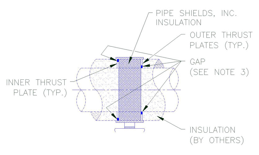
Inner Thrust Plate Detail
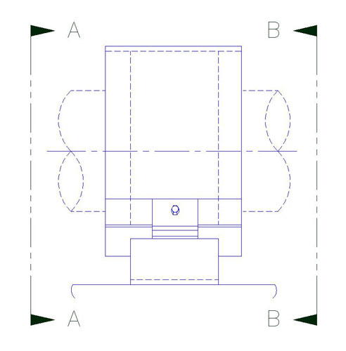
Section A-A
Elevation
Section B-B
Section C-C
Notes:
1. Located the inner thrust plates on the side of the assembly directly opposite the outer thrust plates located on the other side of the unit at all times (see sections A-A and B-B). DO not install inner thrust plates directly over the outer thrust plates.
2. Position the inner thrust plate to provide equal gap (*) between the edges of the inner thrust plate and the two adjacent outer thrust plates as shown above.
3. Insulator to fill gaps as shown with loose insulation before installing pipe insulation.
| Table 1 Bolt Torque & Weld Size (W) | ||||||||
| Pipe Size | ||||||||
(FT-LBS) |
(FT-LBS) |
(FT-LBS) |
(FT-LBS) |
|||||
| 1″ | 5-10 | 3/16 | 10-15 | 3/16 | 10-15 | 1/4 | 10-15 | 1/4 |
| 1.25″ | 5-10 | 3/16 | 10-15 | 3/16 | 10-15 | 1/4 | 10-15 | 1/4 |
| 1.5″ | 5-10 | 3/16 | 10-15 | 3/16 | 10-15 | 1/4 | 10-15 | 1/4 |
| 2 | 5-10 | 3/16 | 10-15 | 3/16 | 10-15 | 1/4 | 10-15 | 1/4 |
| 3″ | 5-10 | 3/16 | 10-15 | 3/16 | 10-15 | 1/4 | 10-15 | 1/4 |
| 4″ | 5-10 | 3/16 | 10-15 | 3/16 | 10-15 | 1/4 | 10-15 | 1/4 |
| 6″ | 5-10 | 3/16 | 10-15 | 3/16 | 20-30 | 1/4 | 10-15 | 1/4 |
| 8″ | 5-10 | 3/16 | 10-15 | 3/16 | 20-30 | 1/4 | 15-20 | 1/4 |
| 10″ | 10-20 | 1/4 | 20-30 | 1/4 | 20-30 | 1/4 | 15-20 | 1/4 |
| 12″ | 10-20 | 1/4 | 20-30 | 1/4 | 20-30 | 1/4 | 20-23 | 1/4 |
| 14″ | 10-20 | 1/4 | 20-30 | 1/4 | 20-30 | 1/4 | 20-23 | 1/4 |
| 16″ | 10-20 | 1/4 | 20-30 | 1/4 | 30-50 | 1/4 | 30-32 | 5/16 |
| 18″ | 10-20 | 1/4 | 20-30 | 1/4 | 30-50 | 1/4 | 33-35 | 5/16 |
| 20″ | 10-20 | 1/4 | 20-30 | 1/4 | 30-50 | 1/4 | ||
| 24″ | 10-20 | 1/4 | 20-30 | 1/4 | 30-50 | 1/4 | ||
| 26″ | 10-20 | 1/4 | 20-30 | 1/4 | 30-50 | 1/4 | ||
| 28″ | 10-20 | 1/4 | 20-30 | 1/4 | 30-50 | 1/4 | ||
| 30″ | 30-50 | 1/4 | 50-60 | 1/4 | 60-75 | 5/16 | ||
| 36″ | 30-50 | 1/4 | 50-60 | 1/4 | 60-75 | 5/16 | ||
| 42″ | 30-50 | 1/4 | 50-60 | 1/4 | 60-75 | 5/16 | ||