Installation Steps

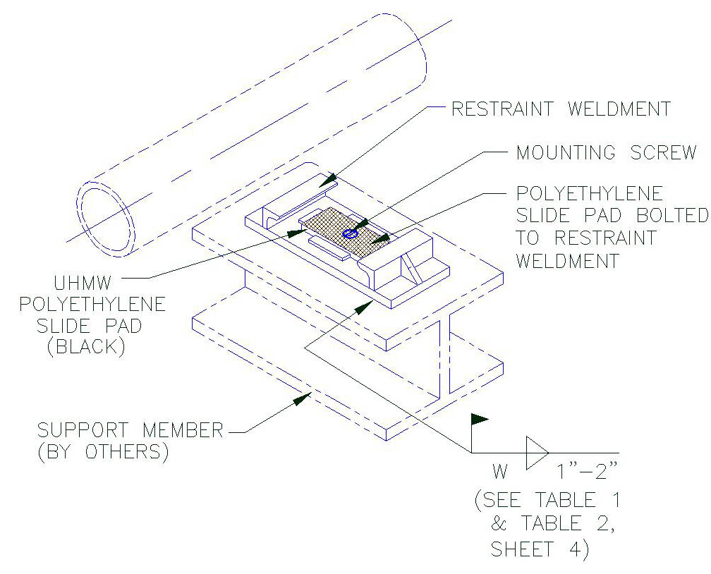
1. A) Remove the mounting screw from the slide pad and slide base restraint weldment.
B) Temporarily separate the slide pad from the restraint weldment.
C) Locate and position the restraint weldment on the steel support to meet the required piping analysis cold settings (see below for P.S.I. recommended cold settings). Please note that required piping analysis cold settings governs over P.S.I. recommendations.
D) When properly positioned, weld restraint weldment to support steel as shown. Select (W) weld size that correspond with the pipe size and model designation of the unit.
E) Place slide pad on restraint weldment and install with the mounting screws.
Model: B3000 – B3300
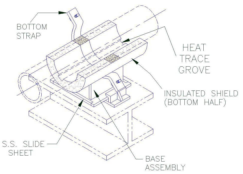
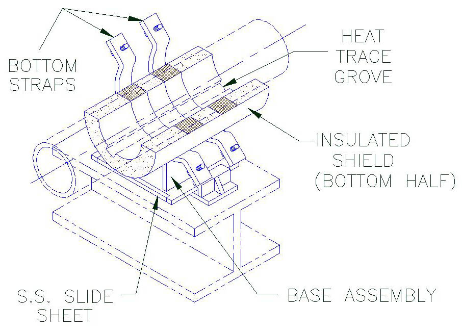
2. Position bottom half of the insulated shield into the base assembly. Ensure that the inserts are properly located over the strap(s) by checking that:
A) Each end of shield shall have equal distance (c) from outer edge of strap (Figure A or A1).
B) The 180° section of the bottom half shield shall be parallel to the support base (Figure 8).
Model: B4000-B4300
3. A) Slide the base assembly and bottom half shield under the pipe.
(B) Position the base assembly on the restraint weldment to allow for anticipated axial travel.
Notes:
When models include heat trace groves, the number and location may vary. Check with design drawings for exact number and location. Ensure that the heat tracing cable is properly positioned inside the grove of the shield.
Model: B3000 – B3300
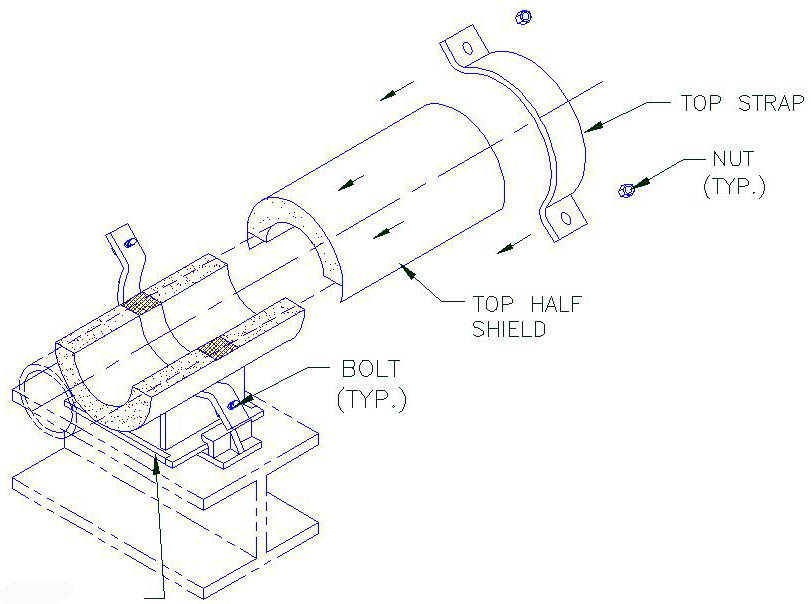
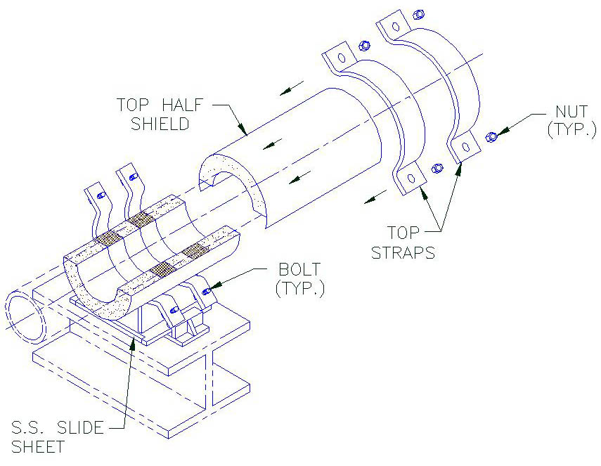
4. A) Slide the top half shield into position above the bottom-half shield.
B) Gently place the top strap into position above the bottom strap and line-up the bolt holes.
Model: B4000-B4300
5. A) Install the bolts, lockwashers and nuts and hand tighten. For ease of bolt torquing, install the bolts with the nuts on top.
B) Apply torque on the bolts. Select torque value that corresponds with the pipe size and model designation of the unit shown on table 1 for model B3000-B3300 and table 2 for B4000-B4300. When tightening, it is recommended that the nut is turned rather than the bolt head and that the bolts are cross-torqued until the required torque has been achieved to obtain an even pressure on the structural insulation.
C) Ensure that the bolts are properly cross-torqued by checking the spacing “B” between the ears to be approximately the same (see Figure B).
Note:
These units are designed for specific axial travel. Prior to tightening of the bolts, the unit may require cold setting (see figure A & A1 for recommended axial cold setting instructions for this unit).
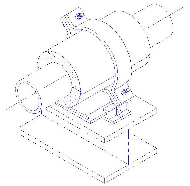
Completed Assembly
Model: B3000 – B3300
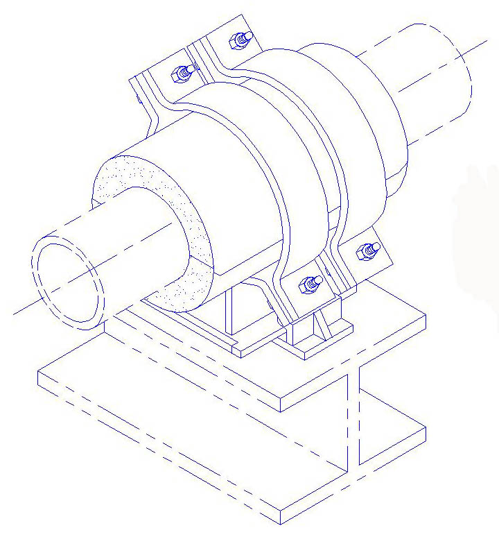
Completed Assembly
Model: B4000-B4300
Axial Cold Settings
A) Position base assembly such that after the support has moved, the center line of the strap (marked by the center line) approximately matches the center line of the restraint weldment (Figure A & A1).
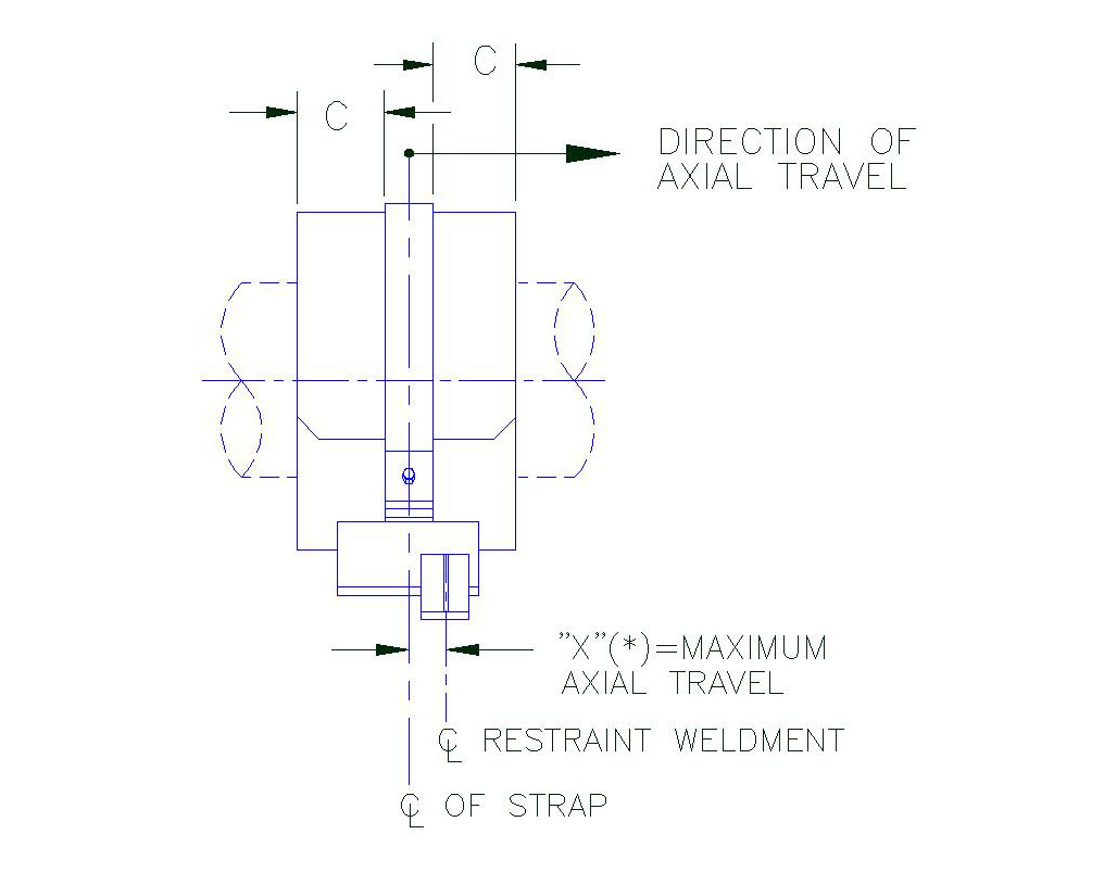
Figure A
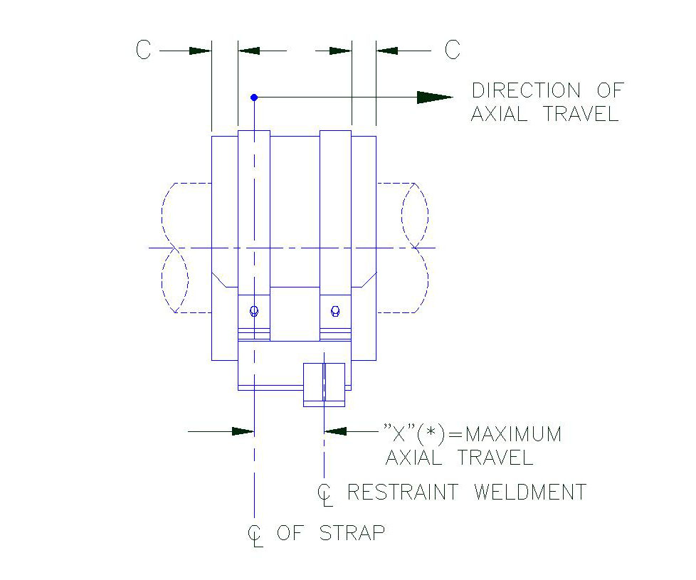
Figure A1
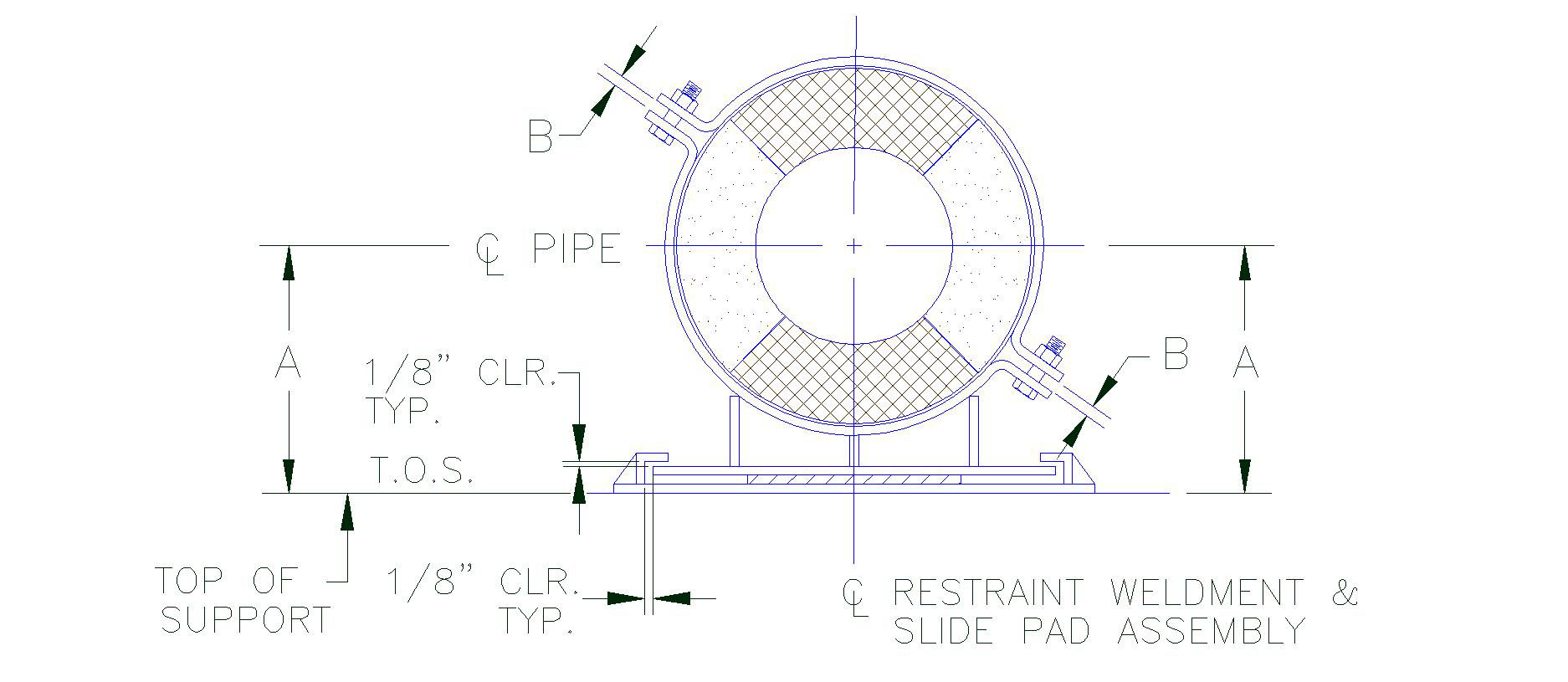
Figure B
| Table 1Bolt Torque & Weld Size (W) | ||||||||
| Pipe Size | ||||||||
(FT-LBS) |
(FT-LBS) |
(FT-LBS) |
(FT-LBS) |
|||||
| .5″ | 3-5 | 3/16″ | 3-5 | 3/16″ | 3-5 | 3/16″ | 3-5 | 3/16″ |
| 1″ | 3-5 | 3/16″ | 3-5 | 3/16″ | 3-5 | 3/16″ | 3-5 | 3/16″ |
| 1.5″ | 3-5 | 3/16″ | 3-5 | 3/16″ | 3-5 | 3/16″ | 3-5 | 3/16″ |
| 2″ | 3-5 | 3/16″ | 3-5 | 3/16″ | 5-7 | 3/16″ | 3-5 | 3/16″ |
| 2.5″ | 3-5 | 3/16″ | 3-5 | 3/16″ | 6-8 | 3/16″ | 3-5 | 3/16″ |
| 3″ | 3-5 | 3/16″ | 5-7 | 3/16″ | 7-9 | 3/16″ | 3-5 | 3/16″ |
| 3.5″ | 3-5 | 3/16″ | 6-8 | 3/16″ | 8-10 | 3/16″ | 6-8 | 3/16″ |
| 4″ | 3-5 | 3/16″ | 7-9 | 3/16″ | 11-13 | 3/16″ | 7-9 | 3/16″ |
| 5″ | 3-5 | 3/16″ | 9-11 | 3/16″ | 13-15 | 3/16″ | 9-11 | 3/16″ |
| 6″ | 7-9 | 1/4″ | 14-16 | 1/4″ | 20-22 | 1/4″ | 14-16 | 1/4″ |
| 8″ | 9-11 | 1/4″ | 18-20 | 1/4″ | 27-29 | 1/4″ | 18-20 | 1/4″ |
| 10″ | 11-13 | 1/4″ | 21-23 | 1/4″ | 32-34 | 1/4″ | 21-23 | 1/4″ |
| 12″ | 12-14 | 1/4″ | 23-25 | 1/4″ | 35-37 | 1/4″ | 23-25 | 1/4″ |
| 14″ | 13-15 | 1/4″ | 27-29 | 1/4″ | 40-42 | 1/4″ | 27-29 | 1/4″ |
| 16″ | 18-20 | 1/4″ | 37-39 | 1/4″ | 55-57 | 1/4″ | 37-39 | 1/4″ |
| 18″ | 20-22 | 1/4″ | 41-43 | 1/4″ | 61-63 | 1/4″ | 41-43 | 1/4″ |
| 20″ | 22-24 | 1/4″ | 43-45 | 1/4″ | 65-67 | 1/4″ | 43-45 | 1/4″ |
| 24″ | 23-25 | 1/4″ | 46-48 | 1/4″ | 69-71 | 1/4″ | 46-48 | 1/4″ |
| 26″ | 25-27 | 1/4″ | 51-53 | 1/4″ | 76-78 | 1/4″ | 51-53 | 1/4″ |
| 28″ | 27-29 | 1/4″ | 55-57 | 1/4″ | 82-84 | 1/4″ | 55-57 | 1/4″ |
| 30″ | 40-42 | 1/4″ | 80-82 | 1/4″ | 120-122 | 1/4″ | 80-82 | 1/4″ |
| 32″ | 42-44 | 1/4″ | 85-87 | 1/4″ | *127-129 | 1/4″ | 85-87 | 1/4″ |
| 36″ | 47-49 | 1/4″ | 93-95 | 1/4″ | *140-142 | 1/4″ | 93-95 | 1/4″ |
| 42″ | 53-55 | 1/4″ | 105-107 | 1/4″ | *158-160 | 1/4″ | 105-107 | 1/4″ |
| 48″ | 60-62 | 1/4″ | 120-122 | 1/4″ | *180-185 | 1/4″ | 120-122 | 1/4″ |
* = Requries A-325 Bolt Material
| Table 2Bolt Torque & Weld Size (W) | ||||||||
| Pipe Size | ||||||||
(FT-LBS) |
(FT-LBS) |
(FT-LBS) |
(FT-LBS) |
|||||
| 1″ | 3-5 | 3/16″ | 3-5 | 3/16″ | 3-5 | 3/16″ | 3-5 | 3/16″ |
| 1.5″ | 3-5 | 3/16″ | 3-5 | 3/16″ | 3-5 | 3/16″ | 3-5 | 3/16″ |
| 2″ | 3-5 | 3/16″ | 3-5 | 3/16″ | 3-5 | 3/16″ | 3-5 | 3/16″ |
| 2.5″ | 3-5 | 3/16″ | 3-5 | 3/16″ | 3-5 | 3/16″ | 3-5 | 3/16″ |
| 3″ | 3-5 | 3/16″ | 3-5 | 3/16″ | 3-5 | 3/16″ | 3-5 | 3/16″ |
| 3.5″ | 3-5 | 3/16″ | 3-5 | 3/16″ | 3-5 | 3/16″ | 3-5 | 3/16″ |
| 4″ | 3-5 | 3/16″ | 3-5 | 3/16″ | 5-7 | 3/16″ | 3-5 | 3/16″ |
| 5″ | 3-5 | 3/16″ | 3-5 | 3/16″ | 7-9 | 3/16″ | 3-5 | 3/16″ |
| 6″ | 3-5 | 1/4″ | 7-9 | 1/4″ | 10-12 | 1/4″ | 7-9 | 1/4″ |
| 8″ | 5-7 | 1/4″ | 9-11 | 1/4″ | 14-16 | 1/4″ | 9-11 | 1/4″ |
| 10″ | 5-7 | 1/4″ | 11-13 | 1/4″ | 16-18 | 1/4″ | 11-13 | 1/4″ |
| 12″ | 6-8 | 1/4″ | 12-14 | 1/4″ | 18-20 | 1/4″ | 12-14 | 1/4″ |
| 14″ | 7-9 | 1/4″ | 13-15 | 1/4″ | 20-22 | 1/4″ | 13-15 | 1/4″ |
| 16″ | 9-11 | 1/4″ | 18-20 | 1/4″ | 28-30 | 1/4″ | 18-20 | 1/4″ |
| 18″ | 10-12 | 1/4″ | 20-22 | 1/4″ | 31-33 | 1/4″ | 20-22 | 1/4″ |
| 20″ | 11-13 | 1/4″ | 22-24 | 1/4″ | 33-35 | 1/4″ | 22-24 | 1/4″ |
| 24″ | 11-13 | 1/4″ | 23-25 | 1/4″ | 34-36 | 1/4″ | 23-25 | 1/4″ |
| 26″ | 13-15 | 1/4″ | 25-27 | 1/4″ | 38-40 | 1/4″ | 25-27 | 1/4″ |
| 28″ | 14-16 | 1/4″ | 27-29 | 1/4″ | 41-43 | 1/4″ | 27-29 | 1/4″ |
| 30″ | 20-22 | 1/4″ | 40-42 | 1/4″ | 60-62 | 1/4″ | 40-42 | 1/4″ |
| 32″ | 21-23 | 1/4″ | 42-44 | 1/4″ | 62-64 | 1/4″ | 42-44 | 1/4″ |
| 36″ | 23-25 | 1/4″ | 47-49 | 1/4″ | 70-72 | 1/4″ | 47-49 | 1/4″ |
| 42″ | 26-28 | 1/4″ | 53-55 | 1/4″ | 79-81 | 1/4″ | 53-55 | 1/4″ |