Installation Steps
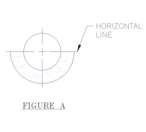
1. Position the bottom half of the insulated hanger shield (insulating structural material and sheet metal jacket) on the pipe at the desired location as shown.
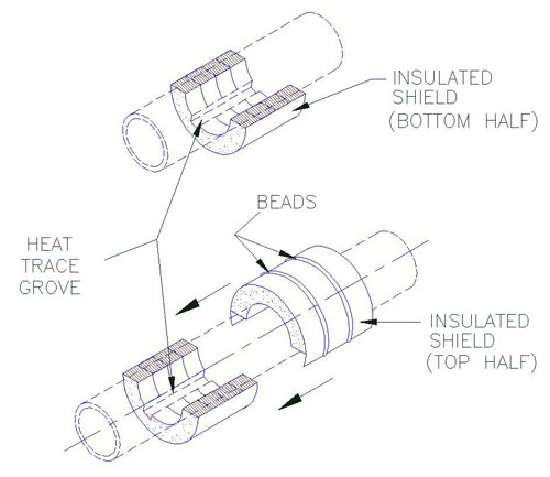
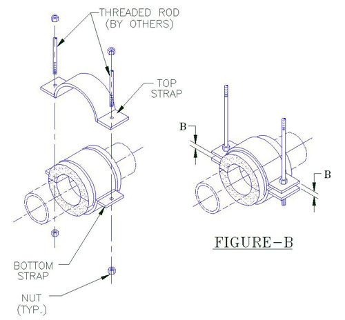 2. A) Gently slide into position the top half of the insulated hanger shield over the bottom half shield as shown. 3. A) Place the straps into position (between the beads) and line up the bolt holes. B) Install the rods through the strap ears, lock washers, nuts and hand tighten. C) Apply torque value on the nuts. D) Select torque value that correspond with the pipe size and model designation of the unit shown on Table 1. When tightening, it is recommended that the nut is turned rather than the rod and that the rod be cross torqued until the required torqued has been achieved to obtain an even pressure on the structural insu-lation. E) To ensure that the bolts are properly cross-torque by checking spacing (B) between the ears shall be approximately the same (see Figure B). Note: When models include heat trace groves, the number and location may vary. Check with design drawings for exact number and location. Ensure that the heat tracing cable is properly positioned inside the grove of the shield.
|
|||||||||||||||||||||||||||||||||||||||||||||||||||||||||||||||||||||||||||||||||||||||||||||||||||||||||
|
|||||||||||||||||||||||||||||||||||||||||||||||||||||||||||||||||||||||||||||||||||||||||||||||||||||||||
Pipe Shields Inc. manufactures pre-insulated pipe supports, slides, guides and anchors and is a subsidiary of Piping Technology and Products, Inc.