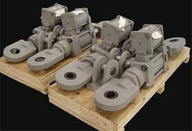
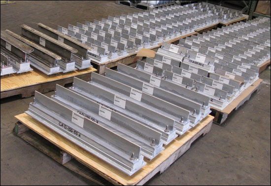
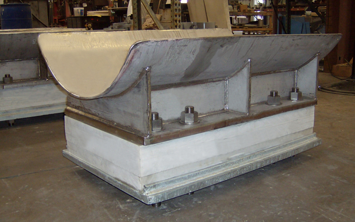
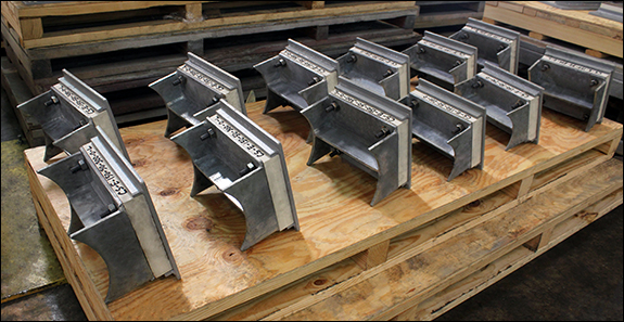
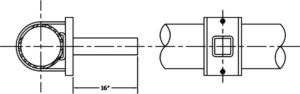
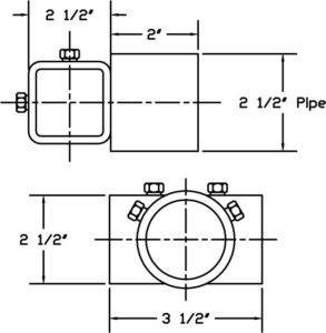
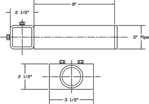
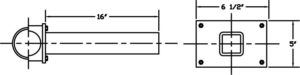
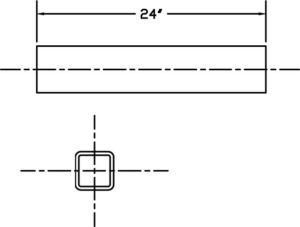
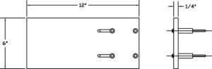
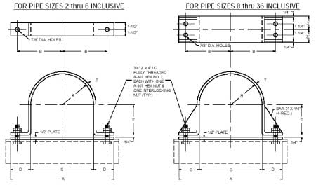
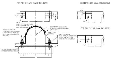
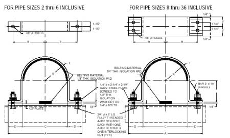
Pipe Clamps
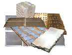
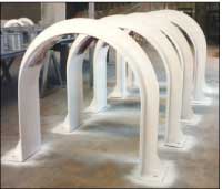
G10 Micarta® can be very cost-effective insulation as compared to Polyurethane foam (PUF), especially for medium and large shoes. It offers tremendous benefits at various stages of a project, including but not limited to:
- Procurement
- Installation
- Handling, transportation, and storage
- Plant Maintenance
Major Advantage of G10 Micarta® Supports for Procurement
G10 Micarta® supports involve fewer steps to manufacture, allowing for a quicker fabrication turnaround. It takes 2-3 weeks less on average than PUF supports for delivery. This enables the ability to catch up on deadlines and reduce downtime.
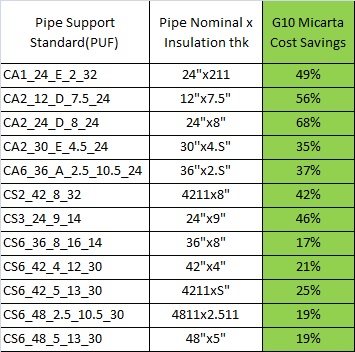
- G10 Micarta® shoes cost less than PUF shoes of the same size, meaning Low Capital Expenses:
Advantages of G10 Micarta® Supports During Construction/Installation
G10 shoes can be sent to the pipe fabricator and can weld directly to the pipe spool, meaning there is minimal installation in the field. It takes 3-5 hours to install a PUF shoe in-field, depending on the size. G10 Micarta® shoes save that FIELD installation time.

Shop welding of G10 Micarta® shoes is much cheaper. As G10 shoes are weld to pipe spool at the fabricator’s shop, they can be inspected and tested in the shop; no inspection and testing in the field. More cost savings as inspection and testing is done at cheaper rates at pipe spool fabricator facilities rather than in the field.
As G10 Micarta® shoes are handled along with the pipe spools, there are fewer chances of missing supports in the field. Less OS&Ds to worry about for both the client and supplier.
Major Advantage of G10 Micarta® Supports while Handling, Transportation & Storage
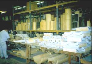
G10 Micarta® supports are less fragile than PUF, making the handling, transportation, and storage of G10 to be trouble-free. No special packaging required, saving the time & the cost of special crating. Stronger G10 supports reduce the chances of accidental damage, thereby the need to re-fabricate the support.
G10 Micarta® supports have insignificant water/moisture absorption rate, this means:
- No structural deterioration in adverse weather, especially in the wake of heavy rain and storms. PUF deteriorates in wet weather or humid climates
- Better life of the support
- Less maintenance and more saving
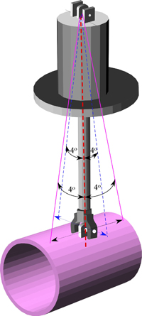
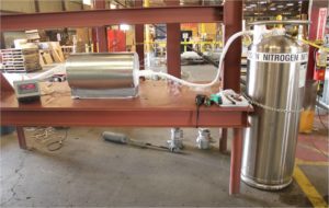
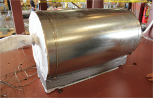
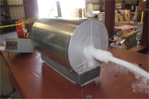
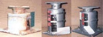
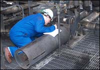
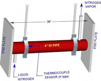
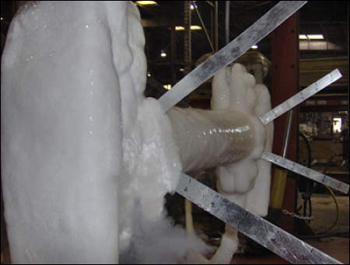
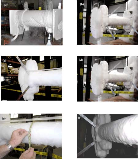
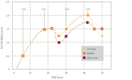
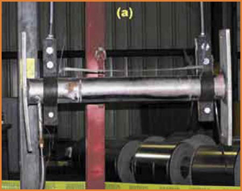
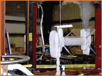
Testing of G10 Micarta® Support
 |
 |
 |
 |
 |
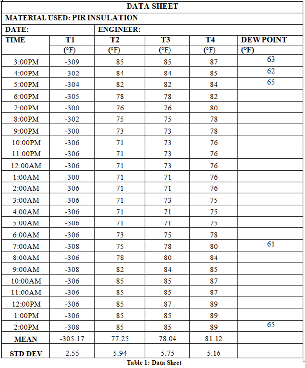
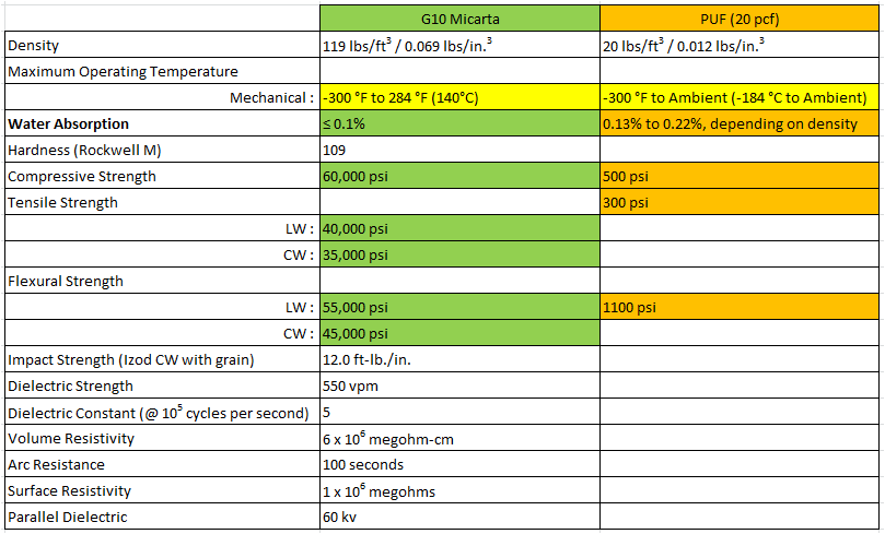
Comparison of G10 Micarta® vs. PUF from previous test reports:
 |
 |
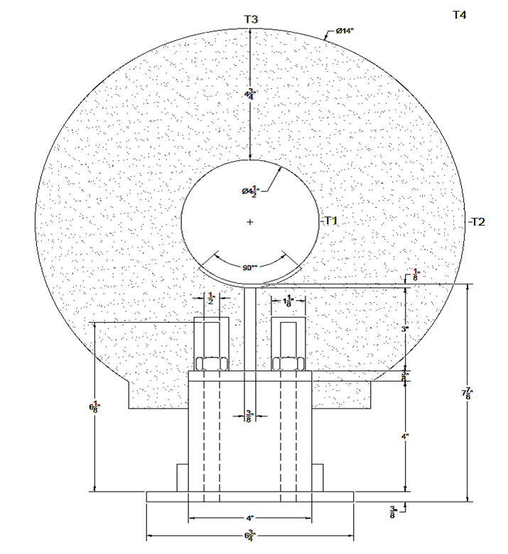
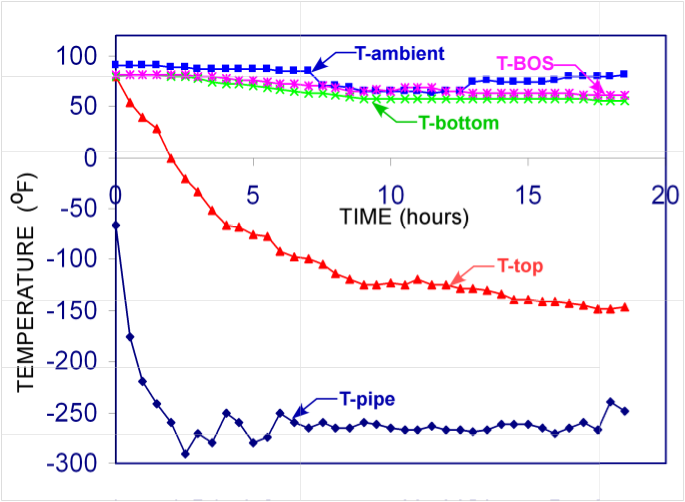
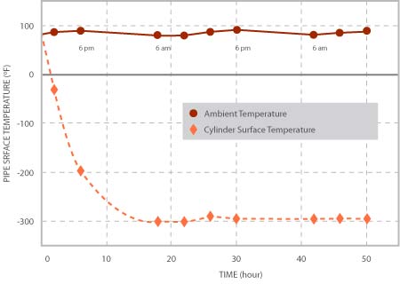
| Time-dependent temperature variations at the stated locations using G-10 Micarta®. (i) T-pipe; (ii) T-top; (iii) T- ambient; (iv) T-Bottom, (v) T-BOS. |
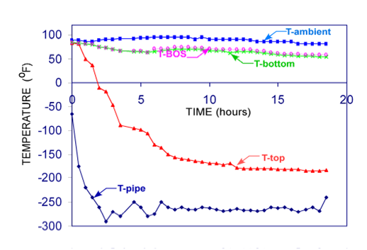
Time-dependent temperature variations at the stated locations using Polyurethane. (i) T-pipe; (ii) T-top; (iii) T- ambient; (iv) T-Bottom, (v) T-BOS. |
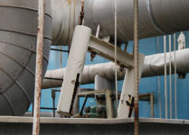


 moving pipe supports. The plates provide a surface friction that has been carefully designed to provide for movements of the piping systems, due to factors such as thermal expansion. In this way, the slide plates allow the system to move easier, keeping it in proper working order.
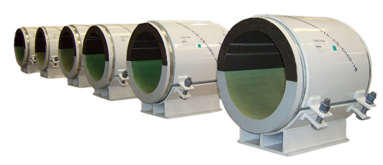
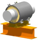
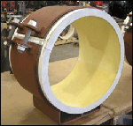 and LNG facilities, there are processes where the “product” inside the piping is at very cold temperatures (down to -320 degrees F in some processes). In these applications, there exists the need to both support and insulate the pipeline while simultaneously allowing and/or limiting movement. The ability to adequately insulate the pipeline helps to increase the efficiency of the piping system by not allowing the “cold” inside the pipe to escape to the environment. However, at points where both supporting and insulating the pipeline is necessary, a special solution is required. Today, several terms have evolved to classify this type of support, including “Insulated Support”, “Cryogenic Support”, and “Cold Support”. Regardless of the term used to describe insulated supports, they all have the same function: to both support and insulate the piping.
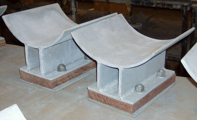
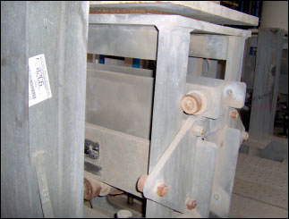
 Vibrations produced by rotating machinery are very common for industrial piping systems. Bracing devices can be used to cope with vibration. Hold downs are one of the most widely used pipe support devices to restrain or dampen pipe vibration. A common location for applying a hold down exists near a compressor. The objective is to limit vibration caused by rotating equipment in order to avoid damage to the surrounding piping system. The hold down restrains the vibration introduced by the compressor as it compresses the gases in the pipe line. Hold downs are effective for the control of vibration and/or movement.
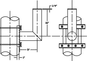
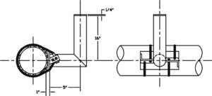
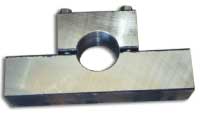 Anchor Type (PTP HD-1)
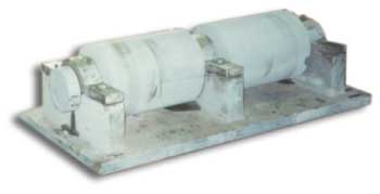
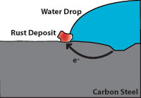
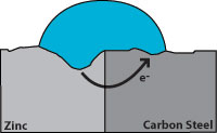
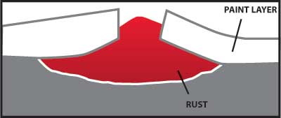
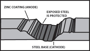
 Effect of corrosion on zinc and carbon steel

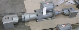
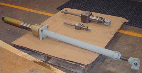
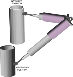
 Similarly to hydraulic snubbers, mechanical snubbers use a telescoping cylinder to permit free movement of the pipe under normal operating conditions. When the threshold acceleration of 0.02 g’s is exceeded, an internal mechanism of the snubber activates, thereby locking the telescoping cylinder and subsequently producing our restraint force.
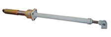
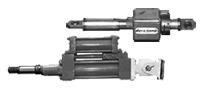 position during either compression or extension modes. However, hydraulic snubbers may show some variation in their dynamic response depending upon the piston location. Therefore, when choosing a hydraulic snubber for a piping system, one must carefully determine the amount of stroke needed to adequately position the snubber piston orientation for optimum functionality.