Suitability of Snubbers for Various Applications

October 9, 2017
By Dr. Hyder Husain Ph.D.
March 9, 2011

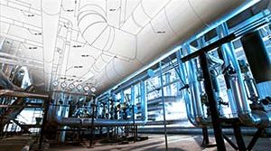
Snubbers are used as restraining devices to control abnormal movement of pipes and equipment due to dynamic events such as earthquakes, turbine trips, safety/relief valve discharge, rapid valve closure, or rupture of pipes. The design of a snubber allows free thermal movement of a component during normal operating conditions, but restrains the component in abnormal conditions.

The snubber restraint forces, as described above, can be generated using either mechanical or hydraulic methods.


Hydraulic Snubbers

Hydraulic snubbers have a piston which is relatively unconstrained during relatively low velocities as would be seen in normal thermal expansion/contraction cycles or slow oscillation of pipes. At high displacement rates, the piston “locks up” and the snubber acts as a rigid restraint.

Hydraulic Snubber

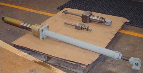
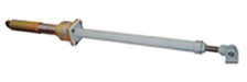
Hydraulic Snubber with an Overall Stroke of 6″

Our commercial hydraulic snubbers have a nominal fluid viscosity of 100cStrokes @ 40°C. Typically, the motion of the snubber-fluid shuts off the valve when the piston velocity reaches 8”/min or more. As a result, the snubber acts as a rigid component and transfers the shock load to the rigid foundation, saving the upstream components.
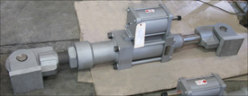

Mechanical Snubbers

Mechanical SnubberSimilarly to hydraulic snubbers, mechanical snubbers use a telescoping cylinder to permit free movement of the pipe under normal operating conditions. When the threshold acceleration of 0.02 g’s is exceeded, an internal mechanism of the snubber activates, thereby locking the telescoping cylinder and subsequently producing our restraint force.


Hydraulic vs. Mechanical Snubbers

Because hydraulic snubbers have fewer internal components, they are preferred in outdoor applications or where a corrosive environment is present. Additionally, hydraulic snubbers can be easily designed to accommodate a wide range of pipe displacement.

Mechanical snubbers are optimum solutions for piping used in high radiation areas such as those seen in nuclear power plants because they do not utilize hydraulic fluid that may become degraded in radioactive environments.

Furthermore, mechanical snubbers require less maintenance overall and are considered “solid state” support components in the piping system. Hydraulic snubbers conversely require a routine inspection to detect leaking seals or loss of hydraulic fluid.


Dynamic Response

In regards to dynamic response, mechanical snubbers react consistently regardless of their Hydraulic Snubber and Mechanical Snubber
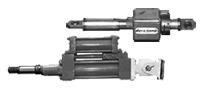
position during either compression or extension modes. However, hydraulic snubbers may show some variation in their dynamic response depending upon the piston location.  Therefore, when choosing a hydraulic snubber for a piping system, one must carefully determine the amount of stroke needed to adequately position the snubber piston orientation for optimum functionality.

Vibration in a Piping System

By Dr. Hyder Husain Ph.D.
January 6, 2011


Cause of Vibration 
All piping systems typically used in industrial application are made of elastic material. Elastic materials vibrate even under small perturbations due to their elastic properties. Since solid materials have a non-zero stiffness factor for both volumetric and shear deformations, these perturbations can generate waves with different velocities depending upon the deformation mode. Volumetric perturbations produce transverse waves while shear perturbations produce longitudinal waves.

External Perturbation  In an ideal situation, pipe vibration would be non-existent if the fluid could flow through the piping system without any disturbances that would cause perturbation. However, in real-life situations, there are many sources that generate perturbation in the piping system and subsequently cause vibration.

Causes of Perturbation Here we can separate the main causes into a few main categories:
(a) Mechanical, (b) Fluid Induced, (c) Transients

(a)  Mechanical:
(i)   Perturbation originating from the pump or compressor.
(ii)  Mechanical perturbation propagating from other moving mechanical components.

(b)  Fluid Induced:
(i)  Flow turbulence (broad band spectra): Function of Reynolds number
(ii)  Multiphase flow: Propagation of slugs (quasi-periodic) and their implosion/explosion may cause serious vibration.
(iii)  Bends & elbows: These produce secondary flows causing further interaction and enhancing strong vertical flows of quasi-periodic nature.
(iv) Valves: Valves cause flow separation and/or direction change which leads to high intensity turbulence (Reynolds number dependent).

(c)  Transients:
(i) Sudden rupture of pipe
(ii) Sudden closure of valve
(iii) External forces on the pipe or piping components

Causes of Perturbation Thorough plant design should ensure that the Eigen-modes and Eigen-values of the overall system subjected to external perturbations should not match those of the piping system when subjected to those same external perturbations.  Low frequency, long waves will cause immediate problems; whereas high frequency, low amplitude vibrations will cause fatigue failures over time.   Therefore, one must be careful in designing the piping system and should use various vibration mitigating devices placed at proper locations.  In addition, proper process controls should be used to reduce vibration especially in multiphase flows.

Snubbers: A General Overview

By Dr. Hyder Husain Ph.D.
December 2, 2010

Introduction: PT&P produces various kinds of snubbers. Why snubbers are used and how they function are briefly discussed here.

What are they?: Snubbers are restraining devices used to control the movement of pipe and equipment during abnormal dynamic conditions such as earthquakes, traveling shock waves caused by turbine trips, safety/relief valve discharge, rapid valve closure or accidental rupture of piping.

Where are they used?: Snubbers are extensively used in various applications including chemical plants, power plants (both conventional & nuclear), refineries, and structures such as suspension bridges and tall rise buildings in earthquake-prone areas.

How do they function?: The design of a snubber allows free thermal movement of components during normal operating conditions. Abnormal conditions activate the snubber to become momentarily rigid (locked condition). While locked, the snubber transmits the transient force to the ground or to a permanent structure without causing any damage to the downstream components. As soon as the transient force ceases, the snubber resumes its normal operation.

Types of Snubbers: There are two types of snubbers: (i) hydraulic and (ii) mechanical snubbers with various types of designs. However, the function of any design is the same—to protect the downstream structure from abnormal shocks. Snubbers are designed for various load ratings depending upon the magnitude of seismic activities and the criticality of fluid induced shocks.

Hydraulic Snubbers: This type consists of either two concentric cylinders or two parallel cylinders and their respective moving pistons. Both the main cylinder and the compensating cylinders are filled with fluid.  The main and the compensating cylinders are connected to velocity limiting valves and a main piston which works in either a push or pull mode. Under normal operating conditions, the valves remain open and allow the piston to move freely under thermal expansion/contraction of the supported component. When the threshold velocity (typically 8 in. per minute) is reached, the valve activates by closing the flow through the valve (also known as valve locking) and the flow through the system stops momentarily. At this point, the main piston that takes the shock load stops moving and the load is transmitted to the ground or to a permanent structure, thus avoiding any damage to the structure downstream of the snubber.  As soon as the shock wave passes, the snubber resumes normal operation.

Hydraulic Snubber
Hydraulic Snubbers

Mechanical Snubber: Similar to hydraulic snubbers, this type of snubber is comprised of a moving cylinder/rod arrangement. Unlike hydraulic snubbers, however, mechanical snubbers use mechanical means to provide the restraint force.

Mechanical Snubbers
Mechanical Snubbers

MSA Mechanical Snubber: With this type of snubber, the linear movement of the rod connected to the piping component is converted to rotary motion. When the centrifugal acceleration exceeds a certain threshold acceleration (typically 0.02g), a centrifugal type clutch flares out and locks at the peripheral slot of the cylinder and restricts linear motion.

Anchor-Darling Mechanical Snubber: With this type of snubber, the linear motion of the central rod that is connected to the structural component is converted to oscillatory motion via a verge mechanism. This oscillatory motion is in turn converted to rotary motion via a set of gears. As the linear velocity increases, the inertia force generated in the oscillating verge and the train of rotating gears increases. The extent of this increase depends upon the amount of inertial mass and gear train’s angular velocities thereby limiting the velocity of the piping components within the safe limit.

Top