By Dr. Hyder Husain Ph.D.
December 2, 2010
Introduction: PT&P produces various kinds of snubbers. Why snubbers are used and how they function are briefly discussed here.
What are they?: Snubbers are restraining devices used to control the movement of pipe and equipment during abnormal dynamic conditions such as earthquakes, traveling shock waves caused by turbine trips, safety/relief valve discharge, rapid valve closure or accidental rupture of piping.
Where are they used?: Snubbers are extensively used in various applications including chemical plants, power plants (both conventional & nuclear), refineries, and structures such as suspension bridges and tall rise buildings in earthquake-prone areas.
How do they function?: The design of a snubber allows free thermal movement of components during normal operating conditions. Abnormal conditions activate the snubber to become momentarily rigid (locked condition). While locked, the snubber transmits the transient force to the ground or to a permanent structure without causing any damage to the downstream components. As soon as the transient force ceases, the snubber resumes its normal operation.
Types of Snubbers: There are two types of snubbers: (i) hydraulic and (ii) mechanical snubbers with various types of designs. However, the function of any design is the same—to protect the downstream structure from abnormal shocks. Snubbers are designed for various load ratings depending upon the magnitude of seismic activities and the criticality of fluid induced shocks.
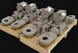
Hydraulic Snubbers: This type consists of either two concentric cylinders or two parallel cylinders and their respective moving pistons. Both the main cylinder and the compensating cylinders are filled with fluid. The main and the compensating cylinders are connected to velocity limiting valves and a main piston which works in either a push or pull mode. Under normal operating conditions, the valves remain open and allow the piston to move freely under thermal expansion/contraction of the supported component. When the threshold velocity (typically 8 in. per minute) is reached, the valve activates by closing the flow through the valve (also known as valve locking) and the flow through the system stops momentarily. At this point, the main piston that takes the shock load stops moving and the load is transmitted to the ground or to a permanent structure, thus avoiding any damage to the structure downstream of the snubber. As soon as the shock wave passes, the snubber resumes normal operation.
 |
|
Hydraulic Snubbers
|
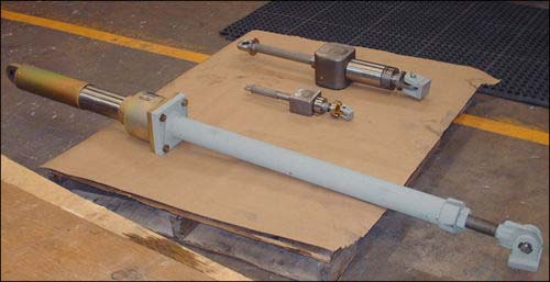
Mechanical Snubber: Similar to hydraulic snubbers, this type of snubber is comprised of a moving cylinder/rod arrangement. Unlike hydraulic snubbers, however, mechanical snubbers use mechanical means to provide the restraint force.
 |
|
Mechanical Snubbers
|
MSA Mechanical Snubber: With this type of snubber, the linear movement of the rod connected to the piping component is converted to rotary motion. When the centrifugal acceleration exceeds a certain threshold acceleration (typically 0.02g), a centrifugal type clutch flares out and locks at the peripheral slot of the cylinder and restricts linear motion.
Anchor-Darling Mechanical Snubber: With this type of snubber, the linear motion of the central rod that is connected to the structural component is converted to oscillatory motion via a verge mechanism. This oscillatory motion is in turn converted to rotary motion via a set of gears. As the linear velocity increases, the inertia force generated in the oscillating verge and the train of rotating gears increases. The extent of this increase depends upon the amount of inertial mass and gear train’s angular velocities thereby limiting the velocity of the piping components within the safe limit.