Installation Steps

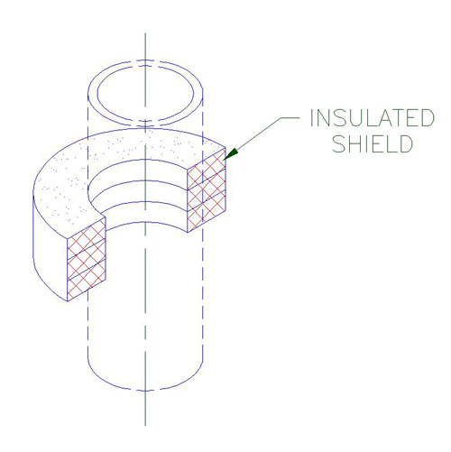
1. A) Position one half of the insulated shield (insulating structural material and sheet metal jacket) on the pipe at the desired location as shown.
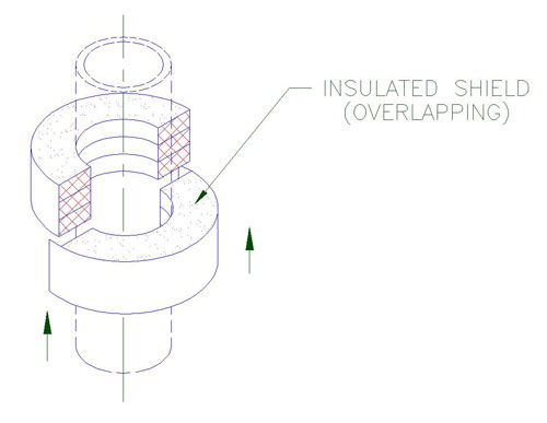
2. A) Gently slide the other half of the insulated shield with the overlapping jacket into position over the previously located half shield.
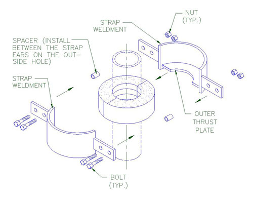
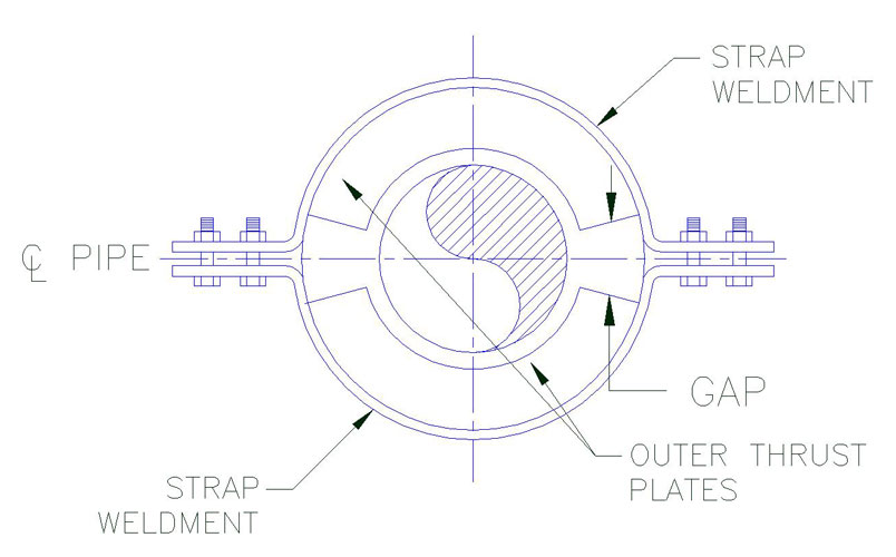
3. A) Assemble strap weldments (strap with shop welded outer thrust plates) and line up the bolt holes.
B) Install the bolts, spacers, lock washers and nuts as shown.
C) Hand tighten nuts before applying the specified torque.
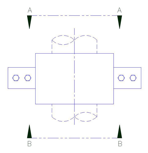
D) Select torque value that correspond with the pipe size and model designation of the unit shown on Table 1. During tightening, it is recommended that the nut is turned rather than the bolt head and that the bolts be crosstorqued until the required torque has been achieved to obtain an even pressure on the structural insulation. To ensure that the bolts are properly crosstorqued by checking the spacing (B) between the ears to be approximately the same.
Note:
When models include heat trace groves, the number and location may vary. Check with design drawings for exact number and location. Ensure that the heat tracing cable is properly positioned inside the grove of the shield.
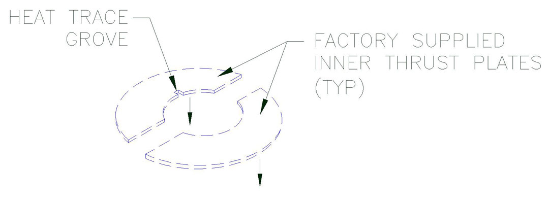
4. Locate and position factory supplied inner thrust plates on the pipe. See sheet 3 for locating and positioning the inner thrust plates on the pipe. When properly positioned, weld them to the pipe as shown (see Table 1).
Note:
In order to act properly as designed, it is important that there is a zero clearance between the inner thrust plates and structural insert. It is recommended that the inner thrust plates be clamped tight against the structural insert before welding and remained clamped until the weld has completely colled-off to avoid or minimize shrinkage and/or distortion due to welding. If there is axial clearance, cut galvanized sheet metal shims to the same outline as the inner thrust plates and install them to reduce this clearance to zero.
Inner Thrust Plate Detail
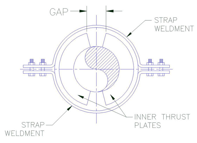
Notes:
1. Located the inner thrust plates on the top side of the assembly and offest 90° fromt he location of the outer
plates which are locate dont he other side of the unit.
2. Position the inner thrust plate to provide equal clearance between the edges of the inner thrust plates as shown
above.
* Gap tolerance:
– 2 1/2″ thick insulation and less + 1/8″
– Greater than 2 1/2″ thick insulation + 1/4″
| Table 1 Bolt Torque |
||||
| Pipe Size | E1000-E10130 | E1100-E1130 | E1200-E1230 | E1300-E1330 |
| Bolt Torque (FT-LBS) |
Bolt Torque (FT-LBS) |
Bolt Torque (FT-LBS) |
Bolt Torque (FT-LBS) |
|
| 3/4 | 3-5 | 3-5 | 3-5 | |
| 1 | 3-5 | 3-5 | 3-5 | |
| 1.25 | 3-5 | 3-5 | 5-7 | |
| 1.5 | 3-5 | 3-5 | 5-7 | |
| 2 | 3-5 | 3-5 | 8-10 | |
| 2.5 | 3-5 | 3-5 | 8-10 | |
| 3 | 3-5 | 8-10 | 13-15 | |
| 3.5 | 3-5 | 8-10 | 13-15 | |
| 4 | 3-5 | 8-10 | 13-15 | |
| 5 | 5-7 | 13-15 | 18-20 | |
| 6 | 6-8 | 13-15 | 23-25 | |
| 8 | 8-10 | 18-20 | 28-30 | |
| 10 | 13-15 | 28-30 | 43-45 | |
| 12 | 13-15 | 28-30 | 43-45 | 58-60 |
| 14 | 18-20 | 38-40 | 58-60 | 73-75 |
| 16 | 18-20 | 38-40 | 58-60 | 88-90 |
| 18 | 23-25 | 48-50 | 73-75 | 98-100 |
| 20 | 23-25 | 48-50 | 73-75 | 98-100 |
| 24 | 23-25 | 56-60 | 88-90 | 118-120 |